Location of system components
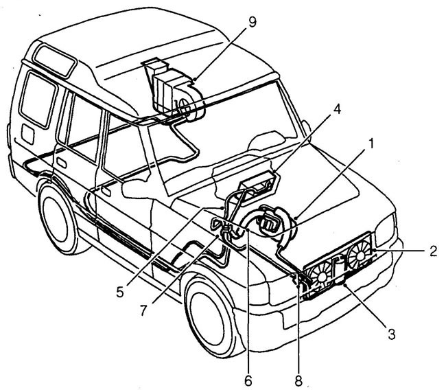
1 - compressor, 2 - condenser, 3 - receiver-dryer, 4 - evaporator, 5 - high-pressure service connection, 6 - low-pressure service connection, 7 - dual pressure switch, 8 - inspection window, 9 - rear evaporator and fan.
Air conditioning system diagram
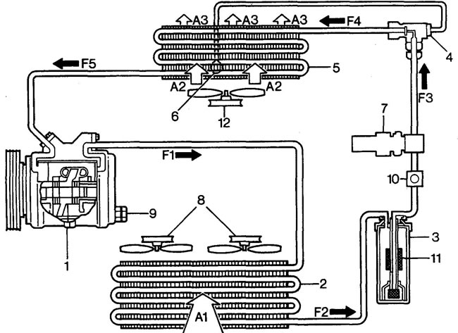
1 - compressor, 2 - condenser, 3 - receiver-dryer, 4 - thermostatic expansion valve, 5 - evaporator, 6 - capillary tube, 7 - double pressure switch, 8 - engine cooling system fans, 9 - compressor safety valve, 10 - inspection window, 11 - dryer, 12 - heater fan, A1 - air from the atmosphere through the condenser, A2 - air from the atmosphere through the evaporator, A3 - cooled air into the cabin, F1 - high-pressure and temperature refrigerant vapor, F2 - high-pressure liquid refrigerant, F3 - high-pressure liquid refrigerant purified from moisture, air and dirt, F4 - vapor and liquid phase of low-pressure and temperature refrigerant, F5 - low-pressure and high-temperature refrigerant vapor.
Original article on the web portal: lrman.ru
Comments on this article