


Contents: Removal ⇩ Installation ⇩
Removal
1. Remove the intake manifold. For more information, refer to Intake Manifold (30.15.02)
2. Evacuate the air conditioning system. For more information, refer to Refrigerant Recovery, Evacuation, and Charging of the Air Conditioning (A/C) System (82.30.02)
3.
CAUTION: Never work on a vehicle supported solely by a jack. Always support the vehicle securely.
Raise and support the vehicle.
4. Drain the coolant from the cooling system. For more information, refer to Draining/Filling Coolant and Bleeding the Cooling System (10/26/01)
5. Remove the floor console. For more information, refer to Floor Console (76.25.01)
6. Remove both door jamb trim panels. For more information, refer to Front Door Jamb Trim Panel (76.13.27)
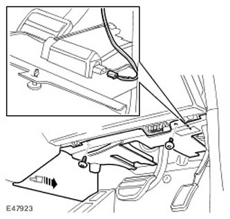
7. Remove the decorative panel from the driver's side.
- Release the clamp.
- Remove two screws.
- Disconnect the electrical connector.
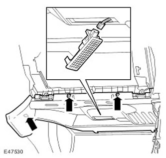
8. Remove the decorative panel from the passenger side.
- Release the clamp.
- Remove two screws.
- Disconnect the electrical connector.
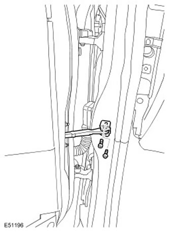
9. Disconnect the door opening limiter from the front body pillar. Unscrew the two Torx bolts.
The article was copied from this resource: www.LRman.ru
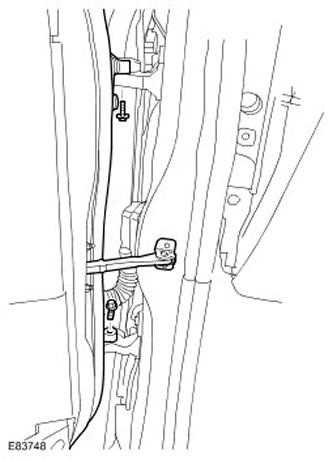
10.
NOTE: At this stage the door is still secured with the appropriate fasteners.
Call an assistant and together release and support the door assembly. Unscrew the two bolts.
11. Disconnect the electrical connector from the A-pillar.
- Remove the sealing sleeve.
- Carefully release and then slide the latch to insert it into the recesses marked with arrows.
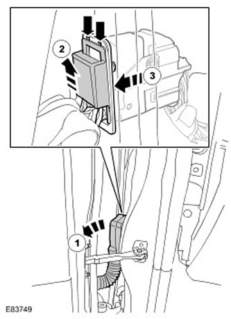
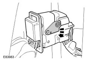
12. Remove the door.
- Remove the sealing sleeve.
- Release the electrical connector.
- Disconnect the electrical connector.
13. Remove the front seats. For more information, refer to Front Seat (78.10.44/99)
14. Release the gear selector cable.
- Remove the clamp.
- Release the cable.
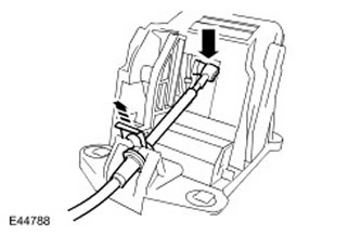
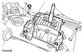
15. Remove the gear selector lever. Unscrew the four bolts.
16. Disconnect the intermediate steering column shaft from the steering column.
- Mark the installation position.
- Unscrew the special bolt and discard the nut.
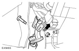
17. Disconnect the two drain pipes from the heater body.
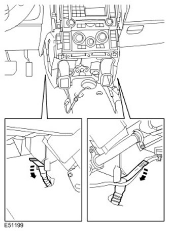
18. Move the central water ducts of the heater body to the side to gain access.
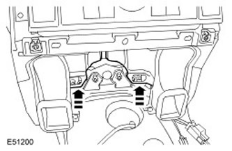
19. Remove the two Torx bolts from the center instrument panel bracket.
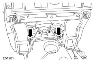
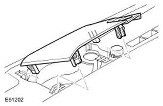
20. Remove the center speaker grille from the instrument panel. Release the four clips.
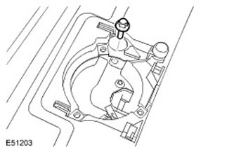
21. Remove the bolt securing the upper section of the instrument panel to the body.
22. Remove the collection chamber panel. For more information, refer to Collection Chamber (80.15.62)
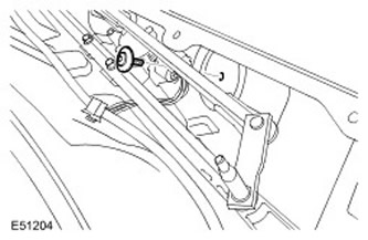
23. Remove the Torx bolt securing the instrument panel bracket to the bulkhead.
24.
CAUTION: Before disconnecting or removing components, clean the area around the contact surfaces and connections. To avoid contamination of the system, plug all open connections.
Disconnect the two heater hoses from the bulkhead. Release the two clamps.
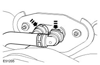
25. Disconnect the two air conditioning pipes from the body. Unscrew the nut.
26.
CAUTION: Immediately plug all refrigerant lines to prevent dirt and moisture from entering.
Disconnect the two air conditioner pipes from the bulkhead.
- Remove the bolt.
- Remove and discard the O-rings.
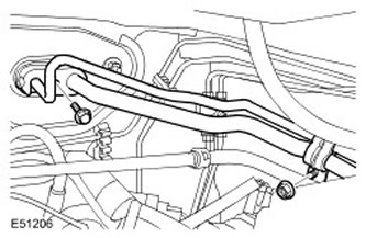
27. Remove the two transition panels. Unscrew the four nuts.
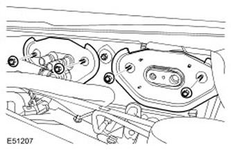
28. Disconnect the three ground wires from the lower part of the A-pillar on the driver's side. Remove the two nuts.
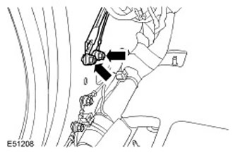
29. Disconnect the five electrical connectors at the bottom of the A-pillar on the driver's side.
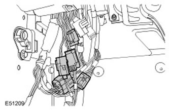
30. Disconnect the three ground wires from the lower part of the front body pillar on the passenger side. Unscrew the two nuts.
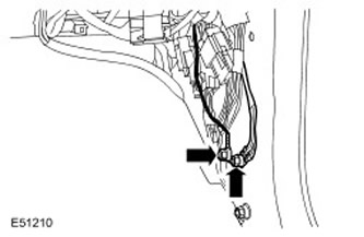
31. Disconnect the five electrical connectors at the bottom of the front pillar on the passenger side.
32. Disconnect the heater motor electrical connector.
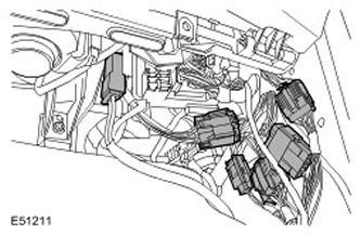
33. Disconnect the two electrical connectors from the Central Junction Box (CJB).
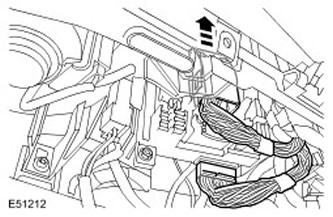
34. Disconnect the two electrical connectors from the instrument panel center reinforcement.
35. Disconnect the fiber optic cables from the instrument panel center reinforcement if the vehicle is equipped with them. Disconnect the electrical connector.
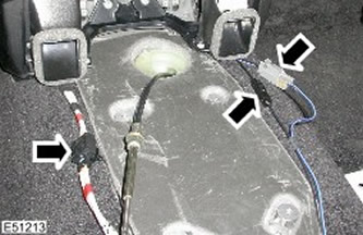
36. From the driver's side: Remove the Torx bolt securing the heater housing to the bulkhead.
37. From the passenger side: Remove the Torx bolt securing the heater housing to the bulkhead.
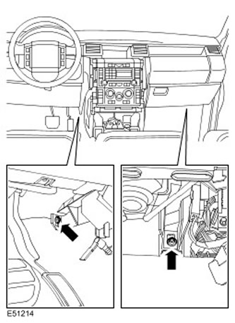
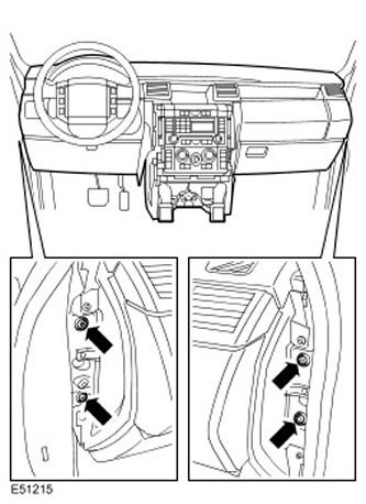
38. With assistance, remove the instrument panel. Remove the four Torx bolts.
Installation
1. Install the instrument panel with assistance. Tighten the Torx bolts to 25 Nm.
2. From the passenger side: Screw in the Torx bolt securing the heater housing to the bulkhead and tighten to 6 Nm.
3. From the driver's side: Screw in the Torx bolt securing the heater housing to the bulkhead and tighten to 6 Nm.
4. Connect the fiber optic cables to the center reinforcement of the instrument panel.
5. Connect the electrical connectors to the instrument panel center reinforcement.
6. Connect the electrical connectors of the Central Junction Box (CJB).
7. Connect the electrical connector of the heater motor.
8. Connect the electrical connectors at the bottom of the A-pillar on the passenger side.
9. Connect the ground wires to the lower part of the front body pillar on the passenger side. Tighten the nuts to 10 Nm.
10. Connect the electrical connectors at the bottom of the A-pillar on the driver's side.
11. Connect the ground wires to the lower part of the A-pillar on the driver's side. Tighten the nuts to 10 Nm.
12. Install the adapter panels. Tighten the nuts to 10 Nm.
13. Secure the air conditioner pipes to the bulkhead.
- Clear the elements.
- Install new O-rings.
- Tighten the bolt to 10 Nm.
15. Secure the heater hoses to the bulkhead.
16. Screw in the Torx bolt securing the instrument panel to the bulkhead and tighten to 25 Nm.
17. Install the collection chamber panel. For more information, refer to Collection Chamber (80.15.62)
18. Screw in the bolt securing the upper part of the instrument panel to the body and tighten to 10 Nm.
19. Install the speaker grille. Secure with clamps.
20. Install the instrument panel centre bracket Torx bolts and tighten to 25 Nm.
21. Install the central air ducts of the heater housing.
22. Connect the drain pipes to the heater body.
23. Attach the intermediate shaft of the steering column. Screw in the special bolt and tighten the new nut with a force of 22 Nm.
24. Install the gear selector lever. Tighten the bolts to 10 Nm.
25. Connect the gear selector lever cable. Install the clamp.
26. Install the front seats. For more information, refer to Front Seat (78.10.44/99)
27. Install the door assembly with assistance.
- Connect the electrical connector.
- Secure the electrical connector.
- Secure the sealing sleeve.
- Tighten the bolts to 10 Nm.
29. Install the driver's side trim panel.
- Connect the electrical connector.
- Secure the clamp.
- Tighten the screws.
- Install the interior light bulb.
- Connect the electrical connector.
- Secure the clamp.
32. Install the floor console. For more information, refer to Floor Console (76.25.01)
33. Fill the cooling system. For more information, refer to Draining/Filling Coolant and Bleeding the Cooling System (10/26/01)
34. Charge the A/C system. For more information, refer to Refrigerant Recovery, Evacuation, and Charging of the Air Conditioning (A/C) System (82.30.02)
35. Install the intake manifold. For more information, refer to Intake Manifold (30.15.02)
Comments on this article