


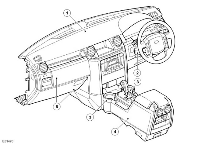
| Item name | Spare part catalog number | Description |
| 1 | - | Instrument panel |
| 2 | - | Steering column cover |
| 3 | - | Cup holders |
| 4 | - | Central console |
| 5 | - | Glove box |
Refrigerating chamber
On some models, the refrigerator compartment is built into the center console between the two front seats.
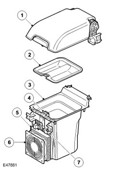
| Item name | Spare part catalog number | Description |
| 1 | Refrigerator compartment cover | |
| 2 | Refrigerator chamber tray | |
| 3 | Container | |
| 4 | Switch | |
| 5 | Thermoelectric cooler radiator | |
| 6 | Fan | |
| 7 | Electrical connector |
The refrigeration chamber is a container with a top lid, with aluminum lining and external thermal insulation. A thermoelectric cooler is installed in the front part of the container. The top of the container is covered with a tray and a lid. A connector on the front wall of the refrigeration chamber connects it to the console wiring harness.
The operation of the thermoelectric cooler is controlled by a two-position switch on the upper front panel of the container. The two-position switch is supplied with DC voltage from the battery via the CJB. When the cooler is switched on, an LED in the switch lights up.
A thermoelectric cooler is a solid-state heat pump that operates on the basis of the Peltier effect. The Peltier effect is that when direct current is passed through junctions of dissimilar conductors, one of the junctions becomes cold and the other heats up. The potential difference at the junctions creates an electric field, when the circuit is closed, the electric charges move against the electric field at one junction, which absorbs heat, and in the direction of the field at the other junction, which releases heat. Thermoelectric coolers have a large number of such junctions that are connected in series and enclosed between ceramic plates that are connected to a radiator and blown by a fan. The cold side of the thermoelectric cooler is in contact with the internal aluminum lining, and the radiator and fan are installed on the outside of the thermal insulation.
Peltier circuit
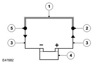
| Item name | Spare part catalog number | Description |
| 1 | Conductor made of material A | |
| 2 | Hot junction | |
| 3 | Conductor made of material B | |
| 4 | Battery | |
| 5 | Cold junction |
When the switch is turned on, the LED lights up and the thermoelectric cooler is supplied with power. The cooler's junctions transfer heat from the aluminum walls to the radiator, which is blown by a fan.
Control system diagram
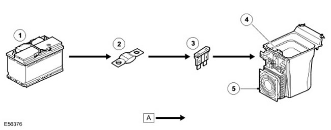
| Item name | Spare part catalog number | Description |
| 1 | Battery | |
| 2 | Fuse link 18E, battery distribution block (BjB) | |
| 3 | Fuse 59P, CJB | |
| 4 | Refrigerator compartment two-position switch | |
| 5 | Thermoelectric cooler |
[The article was taken from this resource: www.lrman.ru]
Comments on this article