car logo Ford
car logo Volkswagen
car logo BMW
car logo Opel
car logo Audi
car logo Toyota
car logo Peugeot
English Русский
Български
Беларускі
Український
Српски
Hrvatski
Română
Polski
Slovenský
Magyar


Main
Freelander
Discovery
Range Rover
Defender
Contacts
Articles

Central reinforcing element of the instrument panel (Discovery 3)

 
  • Main
  • Discovery
  • Discovery 3
  • Body and coating
  • Instrument panel and console
  • Central reinforcing element of the instrument panel
 
        0  
Contents: Removal ⇩ Installation ⇩

Removal


All cars

1. Remove the floor console. For more information, refer to Floor Console (76.25.01)

2. Move the front seats back as far as they will go.

3. Remove the audio unit. For more information, refer to Audio Unit (86.50.81)

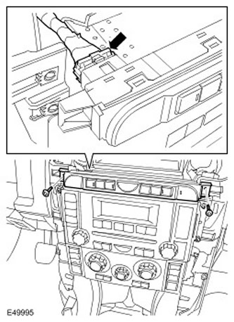
4. Remove the climate control unit. Disconnect the four electrical connectors.
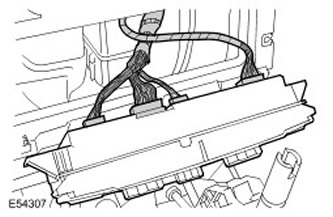
4. Remove the climate control unit. Disconnect the four electrical connectors.


5. Remove the instrument panel console switch block.
  • Remove the two Torx screws.
  • Disconnect the electrical connector.
Disconnect the electrical connector.


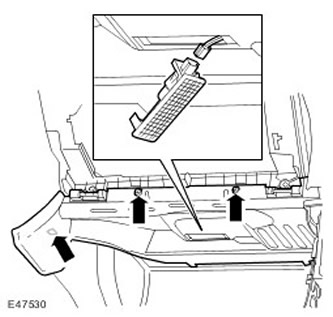
6. Remove the cigarette lighter.
  • Remove the two Torx screws.
  • Release the three clamps.
  • Disconnect the three electrical connectors.
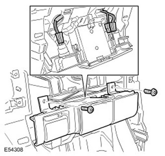
Disconnect the three electrical connectors.


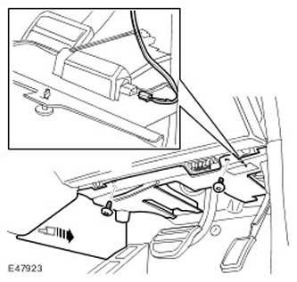
7. Remove the decorative panel from the driver's side.


  • Release the clamp.
  • Remove two screws.
  • Disconnect the electrical connector.
Disconnect the electrical connector.


8. Remove the decorative panel from the passenger side.
  • Release the clamp.
  • Remove two screws.
  • Disconnect the electrical connector.
Disconnect the electrical connector.


9. Remove the two side Torx screws from the instrument panel center reinforcement.
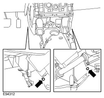
9. Remove the two side Torx screws from the instrument panel center reinforcement.


Cars with navigation system


10.
CAUTION: Cover the fiber optic connections to prevent dust from entering them.; avoid bending fiber optic cables within a radius of less than 30 mm.

Remove the navigation system display module.
  • Remove the four Torx screws.
  • Disconnect the fiber optic cable connector.
  • Disconnect the two electrical connectors.
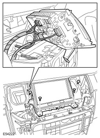
Disconnect the two electrical connectors.


All cars

11. Release the heater duct. Remove the three clamps.
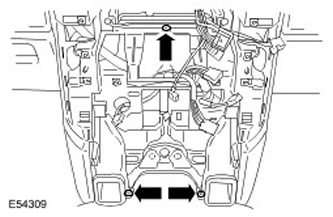
11. Release the heater duct. Remove the three clamps.


12. Release the left wiring harness from the instrument panel center reinforcement. Release the clamp.

13. Release the right wiring harness from the instrument panel center reinforcement. Release the clamp.
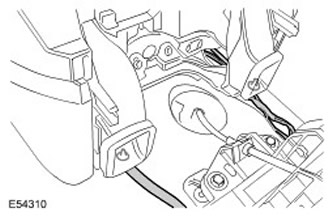
13. Release the right wiring harness from the instrument panel center reinforcement. Release the…


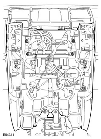
14. Remove the central instrument panel reinforcement.


  • Remove 8 Torx screws.
  • Release the four clamps.
Release the four clamps.


Installation


All cars

1. Install the instrument panel center reinforcement.
  • Secure the clamps.
  • Tighten the Torx screws.
2. Secure the wiring harness. Secure with clamps.

3. Install the heater duct. Install the clamps.

Cars with navigation system.

4. Install the navigation system display module.
  • Connect the electrical connectors.
  • Connect the fiber optic cable connector.
  • Tighten the Torx screws.
All cars

5. Install the passenger side trim panel.
  • Connect the electrical connector.
  • Secure the clamp.
  • Tighten the screws.
6. Install the driver's side trim panel.
  • Connect the electrical connector.
  • Secure the clamp.
  • Tighten the screws.
7. Install the cigarette lighter.
  • Tighten the screws.
  • Connect the electrical connectors.
  • Secure with clamps.
8. Install the instrument panel console switch block.
  • Connect the electrical connector.
  • Tighten the Torx screws.
9. Install the climate control unit. Connect the electrical connectors.

10. Install the audio unit. For more information, refer to Audio Unit (86.50.81)

11. Move the front seats forward as far as they will go.

12. Install the floor console. For more information, refer to Floor Console (76.25.01)


This article is available at russian, bulgarian, belarusian, ukrainian, serbian, croatian, romanian, polish, slovak, hungarian
Article review: Saveliy Ushakov


Previous articles
Instrument cluster specification
The device and technical description of the instrument panel
Removal and installation the instrument panel 4.0L
Removal and installation the instrument panel 4.4L
Removal and installation the instrument panel 2.7L
Switch block on the instrument panel console
Floor console top panel
Upper section of the instrument panel

Current article
Central reinforcing element of the instrument panel


Similar articles from Land Rover repair manuals:
• Instrument panel Freelander 2 (2006-2014)
• Power supply element for the alarm system control panel Freelander 1 (1997-2006)
• Instrument panel Range Rover 3 (2001-2012)
• Description and operating principle of the instrument panel console Defender 2007+ (2007-2016)

Comments on this article


No comments yet


How much will 38 + 28 =


Discovery 3 
  • General information
  • Using the manual
  • Precautionary measures
  • Service Information
  • Technique
  • Health protection
  • Road test
  • Identification codes
  • Jacking and lifting
  • Maintenance - diesel
  • Maintenance - petrol
  • Chassis
  • Suspension
  • Front suspension
  • Rear suspension
  • Wheels and tires
  • Dynamic suspension
  • Cardan shaft
  • Rear drive axle
  • Front drive axle
  • Front axle axles
  • Rear axle axles
  • Brake system
  • Parking brake
  • Hydraulic brake
  • Vacuum brake booster
  • Anti-lock braking system
  • Steering
  • Steering column
  • Power unit
  • Petrol engine 4.0L
  • Petrol engine 4.4L
  • Diesel engine 2.7L
  • Engine cooling
  • Fuel supply
  • Drive units
  • Launch system
  • Ignition system
  • Emission reduction
  • Air filtration
  • Fuel vapor control
  • Electronic control part
  • Car gearbox
  • Clutch
  • All-wheel drive systems
  • Transfer case
  • Exhaust system
  • Fuel tank and lines
  • Acceleration control
  • Electrical equipment
  • Climate control
  • Instruments and control lamps
  • Battery and charging system
  • Information system
  • Lighting and headlights
  • Power distribution
  • Electronic Function Group
  • Body and coating
  • Body elements
  • Interior and body trim
  • Mirrors and glasses
  • Seats
  • Instrument panel and console
  • Handles and locks
  • Windshield wipers and washers
  • Sunroof and bumpers
  • Safety system
  • Body repairs
  • Repair of front end elements
  • Repair of back elements
  • Side panel repair
  • Frame and body mount

Discovery 1 
  • General information
  • Technical specifications
  • Introduction to manual
  • Troubleshooting
  • Power unit
  • Diesel engine Tdi
  • Petrol engine V8i (3.9 l)
  • Petrol engine V8i (4.0 l)
  • Petrol engine Mpi
  • Reducing harmful emissions
  • Fuel system Tdi
  • Fuel system MFi
  • Fuel system SFi
  • Fuel system MPi (MEMS)
  • Cruise control
  • Cooling system (Tdi)
  • Cooling system (V8i)
  • Cooling system (MPi)
  • Exhaust system
  • Transmission
  • Clutch
  • Manual gearbox R380
  • Manual gearbox LT 77
  • Transfer case LT230T
  • Automatic gearbox
  • Cardan shaft
  • Rear axle
  • Front axle
  • Chassis
  • Steering system
  • Front suspension
  • Rear suspension
  • Brake system
  • Wheels and tires
  • Body and interior
  • Passive safety
  • Doors, locks and windows
  • Exterior body parts
  • Interior trim details
  • Seats
  • Electrical equipment
  • Heating and ventilation
  • Air conditioning
  • Windscreen wipers
  • Starting and charging system
  • Equipment and devices
  • Lighting and headlights


LRman.ru © 2013-2026 | Mobile version | Free Lander | Discovery | Range Rover | Defender | Contacts | | Sitemap |
Car repair and service instructions Land Rover: Freelander, Discovery, Range Rover, Defender
We use cookies to make pages load faster and provide a more user-friendly experience 🍪