Coolant flow through the system - manual transmission vehicles without FBH
NOTE: Schematic shown for vehicles prior to MY 2007; for cars from 2007 model year, the scheme is similar.
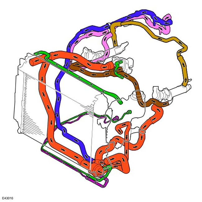
Coolant Flow Through the System - Vehicles with Manual Transmission and FBH
NOTE: Schematic shown for vehicles prior to MY 2007; for cars from 2007 model year, the scheme is similar.
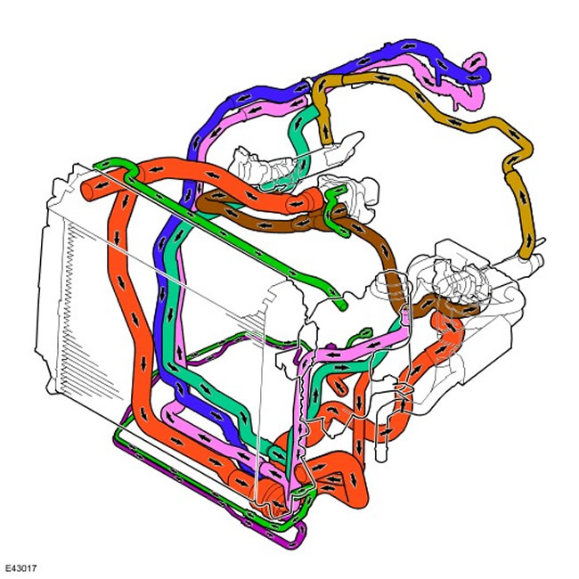
Coolant flow through the system - vehicles with automatic transmission without FBH
NOTE: Schematic shown for vehicles prior to MY 2007; for cars from 2007 model year, the scheme is similar
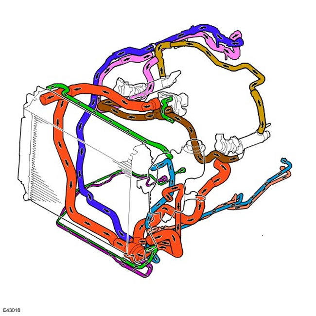
Coolant flow through the system - vehicles with automatic transmission with FBH
NOTE: Schematic shown for vehicles prior to MY 2007; for cars from 2007 model year, the scheme is similar.
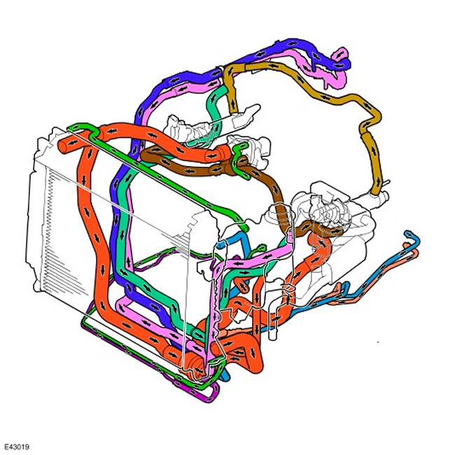
When the engine is running, the coolant pump pulley is driven by the accessory drive belt. In this case, the coolant circulates through the engine cooling jacket and the heater, while the thermostat and bypass valve are closed. When the temperature of the coolant rises, the bypass valve opens and the coolant begins to circulate through it. When the temperature reaches 82°C (180°F), the main thermostat opens, allowing coolant to circulate through the main radiator. As the main thermostat gradually opens (full opening at 95°C (203°F)) the bypass valve gradually closes, causing all the coolant to circulate through the heater or radiator.
As coolant begins to circulate through the radiator, it also begins to flow into the transmission fluid cooler (only for models with automatic transmission) and fuel coolers.
Excess coolant volume due to thermal expansion enters the expansion tank through a hose from the top of the radiator. The expansion tank has an outlet hose connected to the cooling circuit. This hose returns coolant to the system when the engine is cold.
Coolant flows through the radiator from the top of the right reservoir to the bottom of the left reservoir and is cooled by air passing through the core of the radiator. Fluid temperature is monitored by the engine control unit using a coolant temperature sensor (EATING), located in the cylinder head. The signals from this sensor are used by the engine control unit to control the cooling fan and fuel supply in accordance with the engine temperature. For more information refer to Electronic Engine Controls (303-14C Electronic Engine Controls - 2.7L Diesel)
The ECM controls the cooling fan via a pulse width modulated signal that is sent to the fan control module integrated in the engine control module. The PWM frequency is used by the fan control unit to determine the supply voltage to the fan motor.
The engine control unit (ECM) changes the duty cycle of the pulse-width modulated pulse sequence within the range of 0-100%, thereby adjusting the fan speed. If the signal from the engine control unit is outside the range of 0-100%, the fan control unit perceives this as an open circuit or short circuit and turns on the fan at maximum speed to prevent overheating of the engine and transmission.
The engine control module controls the fan in response to signals from the ECT sensor, transmission fluid temperature sensor, intake air temperature sensor, A/C switch, and A/C pressure sensor. For more information refer to Air Conditioning (412-03A Air Conditioning - 4.0L)
In addition, the fan speed depends on the vehicle speed. The ECM regulates the speed of the cooling fans to compensate for the oncoming air flow. The speed signal is transmitted via the CAN bus from the anti-lock brake system control unit.
Pressure control thermostat (PRT)
On one side of the thermostat is 85% of the hot coolant coming from the engine, on the other side is 15% of the cold coolant returning from the lower radiator hose. This allows the thermostat to respond to changing environmental conditions, providing coolant temperature control in both winter and summer. Hot coolant coming from the engine passes through holes in the bypass valve inside a tube that surrounds 85% of the thermostat's active surface. Cold coolant from the radiator passes through the remaining 15% of the thermostat's active area. At low ambient temperatures, engine operating temperature rises by approximately 10°C (50°F) in order to compensate for heat losses from 15% contact with cold coolant returning from the lower hose. This improves heater performance and speeds up engine warm-up.
The bypass valve is held closed by a light spring and provides additional assistance in warming up the engine and heating the heater. When the main valve is closed and the engine is idling, the coolant pump is not providing enough flow and pressure to overcome the spring force and open the valve. As a result, the valve does not allow the coolant to circulate through the bypass channel and directs it only through the heater core. This provides more coolant flow through the heater core, which improves passenger comfort at low temperatures.
As the engine speed increases above idle speed, the coolant pump delivers more flow and pressure than the heater circuit is designed to handle. The increasing pressure acts on the valve, overcomes the spring action and opens the valve, releasing pressure from the heater circuit. The valve then adjusts its opening to maximize coolant flow through the heater core and divert excess coolant through a bypass to keep the engine cool at high speeds. The thermostat then regulates the flow through the radiator, maintaining the optimum engine temperature. The maximum thermostat opening and, accordingly, the maximum flow through the radiator correspond to a coolant temperature of 95°C (203°F).
Comments on this article