Contents: General information ⇩ Engine cooling system ⇩
Vehicles with manual transmission without fuel-fired auxiliary heater (FBH)
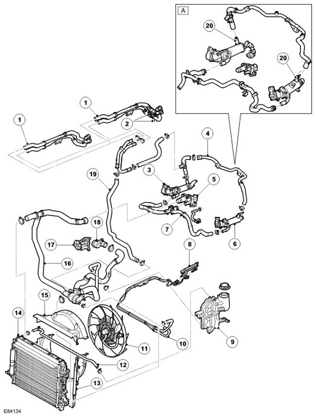
| Item name | Spare part catalog number | Description |
| A | - | Since model year 2007 |
| 1 | - | Heater hoses, inlet and outlet |
| 2 | - | Heater hoses, inlet and outlet, for cars with rear heater (installed additionally) |
| 3 | - | EGR valve |
| 4 | - | EGR valve hose |
| 5 | - | Exhaust pipe assembly |
| 6 | - | EGR valve |
| 7 | - | EGR valve inlet hose |
| 8 | - | Fuel cooler |
| 9 | - | Expansion tank |
| 10 | - | Fuel cooler hose |
| 11 | - | Cooling fan |
| 12 | - | The hose connecting the radiator to the expansion tank |
| 13 | - | Lower casing |
| 14 | - | Radiator |
| 15 | - | Upper casing |
| 16 | - | Hose with thermostat assembly |
| 17 | - | Water pump |
| 18 | - | Inlet manifold connector |
| 19 | - | The hose connecting the heater to the thermostat |
| 20 | EGR thermostat, 2 pcs. (since 2007 model year) |
Cars with manual transmission and FBH
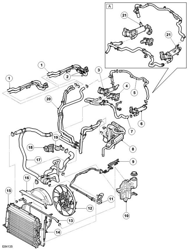
| Item name | Spare part catalog number | Description |
| A | - | Since model year 2007 |
| 1 | - | Heater hoses, inlet and outlet |
| 2 | - | Rear Heater Connections (installed additionally) |
| 3 | - | EGR valve |
| 4 | - | Exhaust pipe assembly |
| 5 | - | EGR valve hose |
| 6 | - | EGR valve |
| 7 | - | EGR valve inlet hose |
| 8 | - | FBH |
| 9 | - | Fuel cooler |
| 10 | - | Expansion tank |
| 11 | - | Fuel cooler hose |
| 12 | - | Cooling fan |
| 13 | - | The hose connecting the radiator to the expansion tank |
| 14 | - | Lower casing |
| 15 | - | Radiator |
| 16 | - | Upper casing |
| 17 | - | Hose with thermostat assembly |
| 18 | - | Water pump |
| 19 | - | Inlet manifold connector |
| 20 | - | FBH hoses, inlet and outlet |
| 21 | EGR thermostat, 2 pcs. (since 2007 model year) |
Cars with automatic transmission without FBH
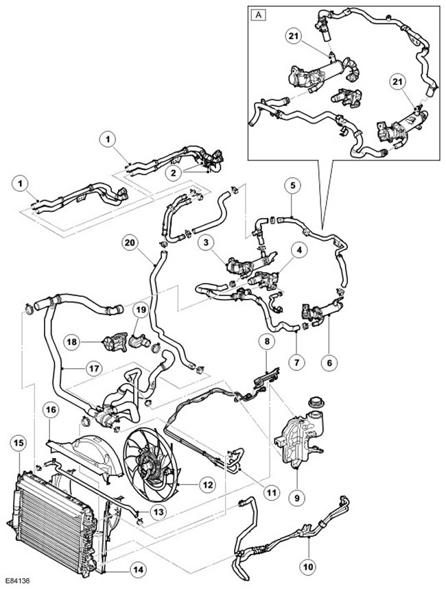
| Item name | Spare part catalog number | Description |
| A | - | Since model year 2007 |
| 1 | - | Heater hoses, inlet and outlet |
| 2 | - | Rear Heater Connections (installed additionally) |
| 3 | - | EGR valve |
| 4 | - | Exhaust pipe assembly |
| 5 | - | EGR valve hose |
| 6 | - | EGR valve |
| 7 | - | EGR valve inlet hose |
| 8 | - | Fuel cooler |
| 9 | - | Expansion tank |
| 10 | - | Transmission Fluid Cooler Lines |
| 11 | - | Fuel cooler hose |
| 12 | - | Cooling fan |
| 13 | - | The hose connecting the radiator to the expansion tank |
| 14 | - | Lower casing |
| 15 | - | Radiator |
| 16 | - | Upper casing |
| 17 | - | Hose with thermostat assembly |
| 18 | - | Water pump |
| 19 | - | Inlet manifold connector |
| 20 | - | The hose connecting the heater to the thermostat |
| 21 | EGR thermostat, 2 pcs. (since 2007 model year) |
Cars with automatic transmission and FBH
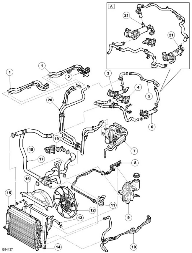
| Item name | Spare part catalog number | Description |
| A | - | Since model year 2007 |
| 1 | - | Heater hoses, inlet and outlet |
| 2 | - | Rear Heater Connections (installed additionally) |
| 3 | - | EGR valve |
| 4 | - | Exhaust pipe assembly |
| 5 | - | EGR valve hose |
| 6 | - | EGR valve |
| 7 | - | FBH |
| 8 | - | Fuel cooler |
| 9 | - | Expansion tank |
| 10 | - | Transmission Fluid Cooler Lines |
| 11 | - | Fuel cooler hose |
| 12 | - | Cooling fan |
| 13 | - | The hose connecting the radiator to the expansion tank |
| 14 | - | Lower casing |
| 15 | - | Radiator |
| 16 | - | Upper casing |
| 17 | - | Hose with thermostat assembly |
| 18 | - | Water pump |
| 19 | - | Inlet manifold connector |
| 20 | - | FBH hoses, inlet and outlet |
| 21 | - | EGR thermostat, 2 pcs. (since 2007 model year) |
General information
A bypass cooling system is used, providing circulation of coolant through the engine and heater circuit with the main thermostat valve closed. The main purpose of the engine cooling system is to maintain the optimum engine temperature when environmental conditions and engine operating mode change. Other functions of the cooling system include heating the car interior and cooling the working fluid of the gearbox and engine oil.
[The article was taken from this resource: www.lrman.ru]
The cooling system includes the following components:
- Radiator
- Intermediate heat exchanger
- Car interior heater core
- Two fuel coolers
- Two exhaust gas recirculation (EGR)coolers
- Fuel fired heater (FBH) (depending on the supply market)
- Coolant pump
- Pressure Regulating Thermostat (PRT)
- Expansion tank
- Fan with electro-viscous coupling
- Connecting hoses and pipelines
Engine cooling system
Coolant is circulated through the system by a centrifugal pump mounted at the front of the engine and driven by an additional poly V-belt. The pump circulates coolant through the cylinder block and cylinder heads through a chamber located in the V of the cylinder block. Some coolant passes through integrated fuel and engine oil coolers. After passing through the engine and oil coolers, the coolant returns to the thermostat housing through a bypass tube. Coolant also passes through the exhaust gas recirculation (EGR) coolers to the heater core and returns to the engine at the pressure regulating thermostat (PRT).
On engines equipped with FBH, coolant flows through EGR coolers to the FBH. (regardless of whether it works or not), and then enters the heater core. The coolant then returns to the PRT on the engine side.
On 2007 and later vehicles, a thermostat is installed in each EGR heat exchanger outlet fitting. These thermostats control the flow of coolant through the EGR heat exchangers, reducing engine emissions and improving engine/heater warm-up.
The PRT housing contains a conventional thermostat that is positioned so that the temperature of its sensing element is determined by the flow of coolant from both the radiator and the bypass channel. As a result, the opening temperature of the thermostat can vary depending on ambient conditions. The PRT also contains a spring-loaded valve that restricts the flow of fluid through the bypass channel. This means that the engine can temporarily run without fluid flowing through the bypass channel, which in turn improves the operation of the cabin heater.
The radiator has a horizontal liquid flow core made of aluminum alloy and a drain cock on the lower right side of the rear side. The lower radiator mounts are on the ends of the radiator tanks. The mounts have rubber bushings that are mounted on the top of the car body rails. The top of the radiator is secured with pins that are passed through rubber bushings mounted on the front element carrier (FEC) above the radiator.
The intermediate heat exchanger is attached to the bottom of the radiator with two pins, which are secured to the fittings of the radiator tanks.
The upper radiator hose is connected to the PRT thermostat via a bypass hose, and the lower hose is directly connected to the thermostat housing outlet pipe.
The expansion tank is installed in front of the left support cup of the suspension in the engine compartment. The expansion tank receives excess amount of working fluid from the cooling system when it expands due to heating and, conversely, when the engine cools down, compensates for its amount when the volume decreases. Air accumulated in the cooling liquid is also discharged through this tank.
Gearbox fluid cooler (only for cars with automatic transmission) is installed on the side of the cold radiator tank. It is located in the middle part of the left radiator tank.
The liquid enters the second fuel cooler from the cold tank side of the radiator from the additional cooling section and returns to the pressure control thermostat housing from the radiator side.
On vehicles equipped with an FBH, this unit is mounted in front of the left suspension support cup in the engine compartment. Coolant always flows through the FBH, regardless of whether it is running or not. The heater exhaust gases are diverted to the left front wheel well. For more information, refer to Auxiliary Heater (412-02B Auxiliary Heating)
To create additional air flow through the radiator core, especially when the vehicle is stationary, a fan with an electro-viscous coupling is used, located behind the radiator. This fan serves the engine cooling system and the air conditioning cooling system. This unit operates like a conventional fan with a viscous coupling, but with an electronic drive for engaging the viscous coupling. The electronic engine control unit (ECM) controls the fan speed by regulating the degree of engagement of the viscous coupling. The degree of engagement of the viscous coupling by the control unit is determined based on the coolant temperature, the air intake and ambient temperature, the oil temperature in the gearbox, and the pressure in the air conditioning system. The fan used has a left-hand rotation.
The speed of the viscous fan is optimally regulated by the ECM to suit all operating conditions.
NOTE: If the electrical connectors are disconnected from the viscous fan, the fan will run at "idle speed" which may cause the engine to overheat. In this case, the ECM will store a corresponding DTC.
Comments on this article