car logo Ford
car logo Volkswagen
car logo BMW
car logo Opel
car logo Audi
car logo Toyota
car logo Peugeot
English Русский
Български
Беларускі
Український
Српски
Hrvatski
Română
Polski
Slovenský
Magyar


Main
Freelander
Discovery
Range Rover
Defender
Contacts
Articles

Windshield — Removal and Installation (Freelander 1)

 
  • Main
  • Freelander
  • Freelander 1
  • Body and coating
  • Interior trim details
  • Windshield — Removal and Installation
 
        0  
Contents: Dismantling ⇩ Installation ⇩
The following equipment is required: Cutting wire with handles, windshield repair kit, sealant gun and suction cups.


Wear protective gloves when working with glass, solvents and primers.


Before performing glass removal and installation work, wear safety glasses.


Dismantling


1. Remove the air intake of the interior ventilation system.

HEATING AND VENTILATION, REPAIR WORKS, Air intake box.


2. Remove the sun visors and their clips.

3. Remove the upper trim panels from the front 'A' pillars.

INTERIOR TRIM PARTS, REPAIR WORK, Replacement of the upper decorative panel of the front 'A' pillar.


4. Remove the retainer from the front of the ceiling panel.

5. Remove the interior rearview mirror.

6. Cover the hood and areas adjacent to the windshield with protective covers.

7. Cover the glass blower holes with protective tape.

8. Cover the interior elements of the car with protective covers.

9. Cut the seal with a knife at the base of the front 'A' pillar.
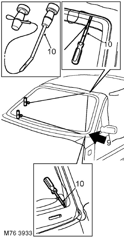
9. Cut the seal with a knife at the base of the front 'A' pillar.


10. Pass the cutting wire through the cut made by the knife and fix the wire to the handles as shown in the figure. The length of the wire between the handles should be approximately 200 mm.


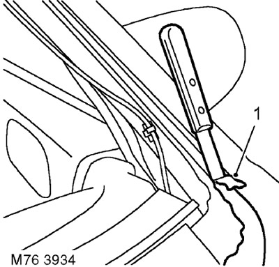
11. Using a cutting wire suitable for this job, carefully cut the seal. Ask for help if necessary. Hold the glass during the final stage of cutting the seal.

If using multi-strand wire, you can use sawing motions when cutting the thickenings of the seal located in the corners of the glass.


Using a sawing motion when cutting single-strand wire can cause the wire to overheat and break.


12. Place suction cups on the glass and, with the help of a partner, remove the glass.

Place the glass on felt-covered supports. Do not place the glass on its edge. A chip on the edge of the glass may cause a crack.


13. Assemble the spacers.

Installation

Installation


1. Carefully remove any remaining sealant from the windshield frame to obtain a smooth surface.

2. Remove any remaining debris with a vacuum cleaner.

3. If the glass is not being replaced: Carefully remove any remaining sealant from the glass to obtain a smooth surface. Do not damage the tinting strip.

4. Install the spacers on the body.

5. With the help of a partner, install the glass on the body.

6. To make installation easier, make marks with adhesive tape.

7. With the help of a partner, remove the glass and set it aside.


8. Clean the windshield frame and windshield edges with solvent.

Do not touch cleaned or etched surfaces with your hands.


9. Apply etching primer to unpainted surfaces of the windshield frame.

10. Apply glue to the glass and let it dry.

11. Apply primer to the etched surfaces of the windshield frame.

12. Apply the activating agent over the old sealant remaining on the frame.

13. Allow the activating reagent to dry.

14. Install the pre-cut tip onto the sealant cartridge, remove the cap and scrape off any hardened residue. Install the cartridge onto the sealant gun.

If necessary, change the shape of the tip to obtain the required cross-section of the sealant layer.
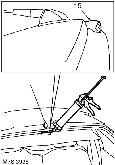

If necessary, change the shape of the tip to obtain the required cross-section of the sealant layer.


15. Apply the sealant to the frame in an even layer as shown in the figure.

16. Avoid allowing gaps or air bubbles to form in the sealant.

17. With the help of a partner, install the glass in place and align it with the supports and tape. Lift the glass and install it on the fixing supports. Lightly press the glass to ensure a tight connection with the sealant.

18. Remove the protective covers and any remaining tape.

19. Check the seal for leaks. Apply additional sealant if necessary. If water is used to check for leaks, allow the seal to dry before checking. Spray the peripheral surface of the glass with water and check if water leaks into the passenger compartment. Mark the leaks. Dry the glass and sealant, then apply additional sealant.


20. Install the upper trim panels onto the A-pillars.

INTERIOR TRIM PARTS, REPAIR WORK, Replacement of the upper decorative panel of the front 'A' pillar.


21. Install the ceiling panel retainer.

22. Install the sun visors and their fasteners.

23. Install the rear view mirror.

24. Install the air intake of the cabin ventilation system.

HEATING AND VENTILATION, REPAIR WORKS, Air intake box.


The sealant needs 6 hours to dry. During this time, leave the car with the windows open and do not slam the doors. If you need to use the car, drive at low speed.


This article is available at russian, bulgarian, belarusian, ukrainian, serbian, croatian, romanian, polish, slovak, hungarian
Article review: Konstantin Nazarov


Previous articles
Sun visor — removal and installation
Lower decorative panel of the luggage compartment of a 3-door car
Lower decorative panel of the luggage compartment of a 5-door car
Upper decorative panel of the luggage compartment of a 3-door car
Upper decorative panel of the luggage compartment of a 5-door car
Replacing the upper decorative panel of the front A-pillar
Replacing the upper decorative panel of the B/C pillar
Lower decorative panel of the middle B-pillar of a 5-door car

Current article
Windshield — Removal and Installation

Next article
Rear side glass — removal and installation


Similar articles from Land Rover repair manuals:
• Windshield washer reservoir Discovery 3 (2004-2009)
• Windshield wiper motor and linkage Discovery 1 (1989-1998)
• Windshield side trim Range Rover 3 (2001-2012)
• Description and operating principle of windshield wipers and washers Defender 2007+ (2007-2016)

Comments on this article


No comments yet


How much will 19 + 12 =


Freelander 2 
  • General information
  • Using the manual
  • Repair technique
  • Precautionary measures
  • Road test
  • Fault codes
  • Identification codes
  • Jacking and lifting
  • Maintenance - Diesel
  • Maintenance - petrol
  • Chassis
  • Suspension
  • Front suspension
  • Rear suspension
  • Wheels and tires
  • Terrain response
  • Transmission system
  • Cardan shaft
  • Rear drive axle
  • Rear axle shafts
  • Front axle shafts
  • Brake system
  • Parking brake
  • Hydraulic brake
  • Brake booster
  • Anti-lock braking system
  • Exchange rate stability
  • Steering
  • Steering column
  • Power unit
  • Engine device
  • Engine repair
  • Description of the cooling system
  • Cooling system repair
  • Fuel supply
  • Drive units
  • Launch system
  • Ignition system
  • Exhaust toxicity
  • Air filtration
  • Fuel vapor control
  • Electronic control part
  • Automatic gearbox
  • Gearbox cooling
  • Automatic transmission controls
  • Mechanical transmission
  • Transfer case
  • Exhaust system
  • Fuel tank and lines
  • Speed control
  • Electrical equipment
  • Climate control system
  • Climate control
  • Additional climate control
  • Instrument panel
  • Sound signal
  • Information and messages
  • Assistance with parking
  • Battery and alternator
  • Information and entertainment
  • Outdoor Lighting
  • Interior lighting
  • Communication network
  • Wiring harnesses
  • Anti-theft system
  • Multifunctional modules
  • Body and coating
  • Body front panels
  • Lockable body parts
  • Interior trim
  • Rear view mirrors
  • Car seats
  • Glass, frames and mechanisms
  • Instrument panel and console
  • Handles, locks, latches
  • Windshield wipers and washers
  • Sunroof
  • Bumpers
  • Seat belt system
  • Restraint system
  • Body repairs
  • Front end repairs
  • Roof element repairs
  • Side panel repairs
  • Tailgate repairs
  • Subframe and mounts

Freelander 1 
  • General information
  • Using the manual
  • Precautionary measures
  • Technique
  • Specifications
  • Connection tightening torques
  • Maintenance
  • Power unit
  • Diesel engine Td4
  • Petrol engine K1.8
  • Piston group K1.8
  • KV6 petrol engine
  • Piston group KV6
  • Decreased toxicity
  • Motor control EDC
  • Engine management MEMS
  • Motor control Siemens
  • Fuel supply diesel Td4
  • Fuel supply for K1.8 engine
  • Fuel supply of KV6 engine
  • Cooling diesel Td4
  • Engine cooling K1.8
  • Engine cooling KV6
  • Exhaust system Td4
  • Exhaust system K1.8
  • Exhaust system KV6
  • Clutch
  • Mechanical transmission
  • Transfer case
  • Automatic gearbox
  • Chassis
  • Drive shafts
  • Rear axle and final drive
  • Steering
  • Front suspension
  • Rear suspension
  • Brake system
  • Body and coating
  • Passive safety
  • Doors, locks and glass
  • Exterior body parts
  • Interior trim details
  • Seats
  • Roof hatch
  • Roof
  • Body geometry
  • Body parts repair
  • Sealing and corrosion
  • Electrical equipment
  • Heating and ventilation
  • Air conditioning
  • Windshield wipers and washers
  • Starting engine and charging
  • Lighting and headlights
  • Control modules
  • Safety system
  • Window management
  • Entertainment systems
  • Wiring harnesses
  • Governing bodies
  • Devices


LRman.ru © 2013-2026 | Mobile version | Free Lander | Discovery | Range Rover | Defender | Contacts | | Sitemap |
Car repair and service instructions Land Rover: Freelander, Discovery, Range Rover, Defender
We use cookies to make pages load faster and provide a more user-friendly experience 🍪