Contents: General information ⇩ Electronic control units ⇩ Equipment ⇩ Seat belt buckles ⇩ High strength steels ⇩ Elimination of deformations ⇩ Body repair stand ⇩ Inspection ⇩
General information
For simplicity, the weld type is only indicated in the drawings on the following pages where it differs from that used in vehicle production.
Welding seams used in repair work are indicated in the drawings as follows:
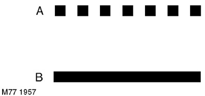
- a Single or multiple spot welding
- b Continuous weld in inert gas
When carrying out welding work, the following rules must be observed.
- Where spot welding was used in the manufacture of the body, spot welding should also be carried out when replacing parts, if possible. In these repeated welds, the weld points should be spaced 30 mm apart.
- When spot welding, it is recommended to test samples of the same metal welded with the same equipment for delamination. These tests will ensure that the equipment used will provide high-quality welding. If spot welding is not possible, a plug weld should be performed.
- Electrodes used for manual spot welding with a welding gun should not be longer than 300 mm.
- Single-sided spot welding is not permitted.
- Brazing and gas welding are not permitted EXCEPT in cases where they were used in the production of the vehicle.
- When joining three or more sheets of metal, inert gas plug welding should be used to ensure a strong joint.
- Inert gas plug welding should be used in cases where it is impossible to use a spot welding machine due to difficulty of access. When replacing a factory spot weld, holes of approximately 8 mm in diameter must be drilled or punched, after which inert gas plug welding must be performed. The number of plug welding spots must exactly correspond to the number of factory welding spots that were drilled.
- After removing the spot weld, each hole in the existing panel must be filled with a corresponding section of the plug weld in inert gas.
Electronic control units
The electronic control units installed in the vehicle make it necessary to take precautions when performing repair welding work. Intense heating and vibration that occur during welding work can cause damage to the electronic units.
In particular, certain precautions must be taken when removing or disconnecting the airbag control unit.
Equipment
Before starting any diagnostic procedure, make sure that all equipment is working properly and all cables and connectors are in good condition. This applies in particular to electronic control units.
Seat belt buckles
Seat belt anchor points play an important role in vehicle safety. It is important to follow all factory specifications when performing repair work on these parts. Please note that HSLA alloy is used for seat belt anchor points.
Therefore, if possible, use the factory seat belts complete with locking and fastening parts. Panel cuts should be made in such a way as not to damage the seat belt fastening parts.
All welds located within 250 mm of the seat belt attachment points must be carefully checked for strength, including areas between weld points.
Caution: Damaged body parts where seat belt anchorages are located MUST be completely replaced with new ones, as the welds located in these areas affect safety and must not be damaged.
High strength steels
Body panels are now often made of high-strength steels to improve passive safety and reduce body weight. Since high-strength steel panels cannot be visually identified during repair work and since they are more sensitive to increased heat than low-carbon steels, it is recommended that the following work methods are always followed.
Despite the differences in the details of performing individual repair work, the following Rules for Repairing Body Panels have been developed to facilitate repairs and reduce the amount of work. If it is necessary to deviate from these Rules during a particular type of body repair, the relevant information is included in the description of the technology for performing the operations.
Elimination of deformations
If possible, deformation of the structural elements of the body should be eliminated by mechanical action without heating the parts. Do not try to straighten the part in one go. Repeat the actions, alternating them with the removal of mechanical force and using these pauses to check the geometry of the part.
Body repair stand
Unless the repair involves decorative body panels, it should be performed on a body repair stand to ensure that the impact deformation has not spread to more distant elements of the body structure. Placing the vehicle on a body repair stand ensures that repair or replacement of individual panels will not cause additional distortion of the body geometry. If this method fails to restore the original geometry of the component, the damaged load-bearing body components must be replaced. Damaged sections of panels should be cut out with a high-speed saw, NOT an oxyacetylene torch. As a rule, all transverse dimensions of the body are symmetrical about the longitudinal axis of symmetry. Therefore, the initial diagnosis of body deformation should be carried out by diagonal measurements and an assessment of the discrepancies in the measurements.
Inspection
Each road traffic accident causes various types of damage to the body. The organization of repair work is determined by the extent of damage to the body and the equipment that can be used for repair. Most body damage can be detected visually, which allows for an approximate assessment of its severity. Sometimes the deformation from the impact extends beyond the directly damaged area. It is necessary to accurately determine the degree of deformation so that as a result of repair the supporting elements of the body take their original shape. Initial diagnostics can be performed using a plumb line and calipers. Accurate measurement of body deformations can be performed using special devices. If it is necessary to replace supporting elements of the body during repair, it is recommended to use a body repair stand.
Comments on this article