car logo Ford
car logo Volkswagen
car logo BMW
car logo Opel
car logo Audi
car logo Toyota
car logo Peugeot
English Русский
Български
Беларускі
Український
Српски
Hrvatski
Română
Polski
Slovenský
Magyar


Main
Freelander
Discovery
Range Rover
Defender
Contacts
Articles

Panel replacement procedure (Freelander 1)

 
  • Main
  • Freelander
  • Freelander 1
  • Body and coating
  • Body parts repair
  • Panel replacement procedure
 
        0  
Contents: Removal the panel ⇩ Preparation of old surfaces ⇩ Preparing new mating surfaces ⇩ Installation and alignment ⇩ Welding ⇩
These materials are intended to familiarize you with the basic methods of removing and replacing damaged panels. The standard method may vary slightly depending on the vehicle being repaired. The main goal of repair operations involving the removal and replacement of body panels is to ensure maximum compliance with the Land Rover factory standards.

Removal the panel
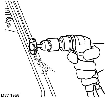

Removal the panel


1. Expose the spot weld. For spot welds hidden under the coating, use an abrasive wheel or wire brush mounted on a pneumatic drill or a regular hand-held wire brush.

NOTE: On wheel arch surfaces, it may be necessary to soften the protective coating using a hot air gun to access the spot weld.
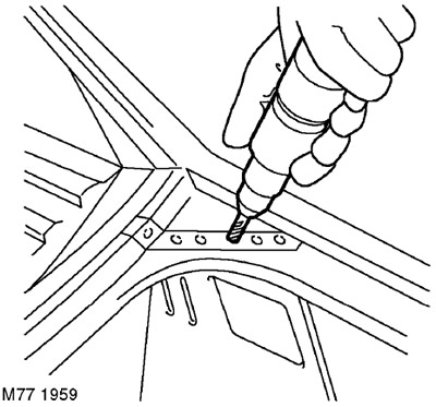

NOTE: On wheel arch surfaces, it may be necessary to soften the protective coating using a hot air…


2. Drill out the weld spots using a cobalt drill.
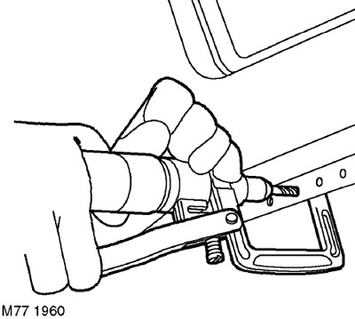


2. Drill out the weld spots using a cobalt drill.


3. A clamp-type spot weld removal device can be used for this purpose.
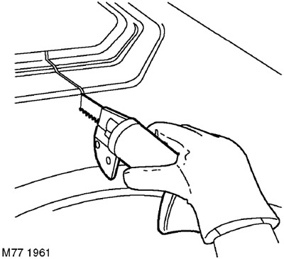
3. A clamp-type spot weld removal device can be used for this purpose.


4. Cut out the damaged area of the panel using a pneumatic saw.

NOTE: On some panel joints joined by MIG welding or brazing, the weld or brazing should be removed with an abrasive tool if possible before cutting the panel.

NOTE: On some panel joints joined by MIG welding or brazing, the weld or brazing should be removed…


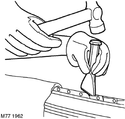
5. Disassemble the spot weld joint and remove the remaining damaged panel using a hammer, punch, chisel and pliers.


Preparation of old surfaces

Preparation of old surfaces


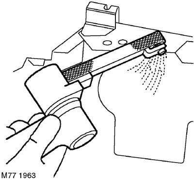
1. Clean all panel joints to a smooth metallic shine using a belt-type abrasive tool.

NOTE: Before stripping, remove any remaining sealant with a hot air gun to reduce the risk of toxic fumes from being released when the metal is heated.


Caution: This equipment should be used with caution, avoiding intense heating of parts.

Caution: This equipment should be used with caution, avoiding intense heating of parts.


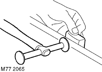
2. Straighten the joint of the old panel using a support block and a hammer.

Preparing new mating surfaces

Preparing new mating surfaces


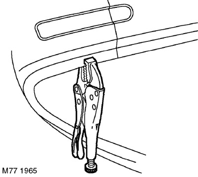
1. Mark the area of the new panel and cut it to size, leaving an allowance of approximately 50 mm to overlap the joint of the existing panel. Check that the new panel or area fits with the adjacent panels (for example, a side panel should fit with a door or boot lid). Secure the new panel with clamps.
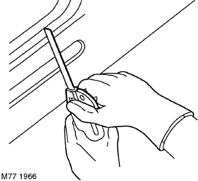


1. Mark the area of the new panel and cut it to size, leaving an allowance of approximately 50 mm…


2. Trim the old and new panels to form the joint of the desired shape. Remove all clamps and remove any scrap metal.
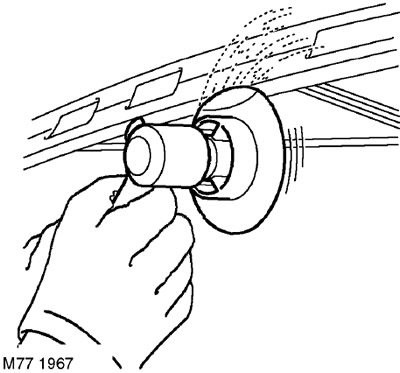
2. Trim the old and new panels to form the joint of the desired shape. Remove all clamps and remove…


3. Prepare the edges of the joint of the new panel by cleaning them to a metallic shine. This should be done both from the outside and from the inside.
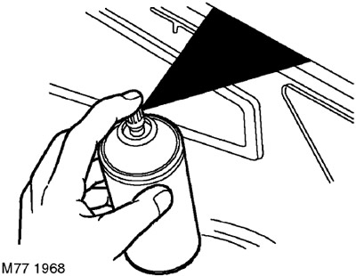
3. Prepare the edges of the joint of the new panel by cleaning them to a metallic shine. This…


4. Apply the appropriate joint preparation compound to the weld areas using a brush or aerosol can.
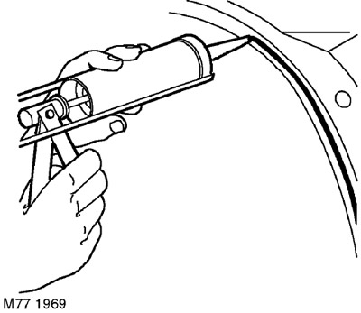


4. Apply the appropriate joint preparation compound to the weld areas using a brush or aerosol can.


5. Apply sealing paste to the mating surfaces of the panels.

Installation and alignment


1. Place the new panel and align it with the panel to be joined. Secure the panel to be installed using special welding clamps. If an enveloping weld is required, install a clamp on the edge of the old panel or install a clamp behind the joint.

NOTE: In cases where it is difficult to secure the panel with welding clamps, tack weld the parts.


Welding

Welding


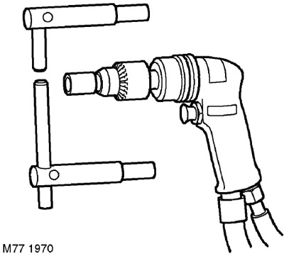
1. Select spot welding equipment and use a cutting machine to shape the ends of the electrodes. The diameter of the electrode end should be equal to twice the thickness of the sheet to be welded plus 3.0 mm.

CAUTION: Use electrodes no longer than 300 mm.


NOTE: To maintain welding efficiency, it is necessary to periodically clean and reshape the electrode tips.


NOTE: To maintain welding efficiency, it is necessary to periodically clean and reshape the…


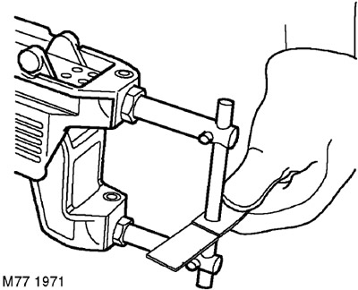
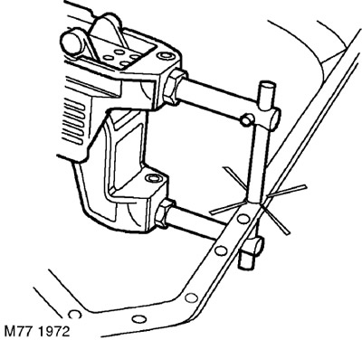
2. Install the spot welding brackets and test the equipment for proper operation using a piece of the material to be welded. If you do not have special testing equipment, test the weld strength. When applying force to separate the welded parts, the metal around the weld point should break before the weld point.
2. Install the spot welding brackets and test the equipment for proper operation using a piece of…


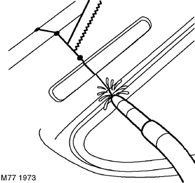
3. If access to the parts allows, use welding equipment for spot welding with resistance heating. If possible, use a welding monitor to control the quality of the weld.
3. If access to the parts allows, use welding equipment for spot welding with resistance heating.…


4. Tack weld the panels to be joined and, if necessary, check their fit and edge alignment. The gap between the weld spots should minimize warping. A hacksaw blade can be used for checking.
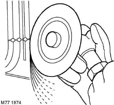


4. Tack weld the panels to be joined and, if necessary, check their fit and edge alignment. The gap…


5. Clean the weld areas in inert gas using a 36 abrasive disc or, if access is difficult, using a belt cleaning device.
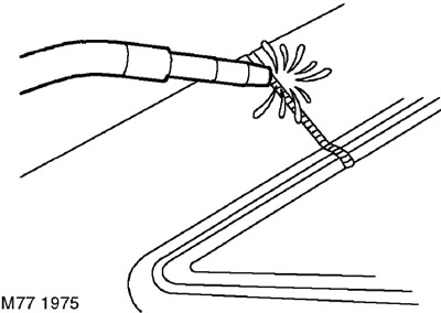
5. Clean the weld areas in inert gas using a 36 abrasive disc or, if access is difficult, using a…


6. Connection by intermittent welding in inert gas.
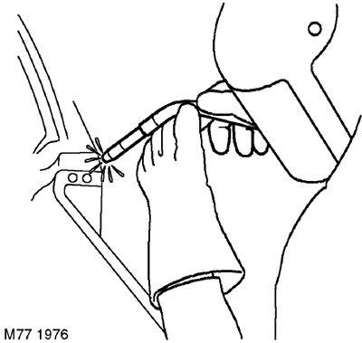
6. Connection by intermittent welding in inert gas.


7. Always perform plug welding in inert gas if the thickness of the sheets to be welded or difficult access make spot welding impossible. Plug welding can be performed using holes left after spot welding has been drilled or through specially drilled or punched holes of approximately 8 mm in diameter.
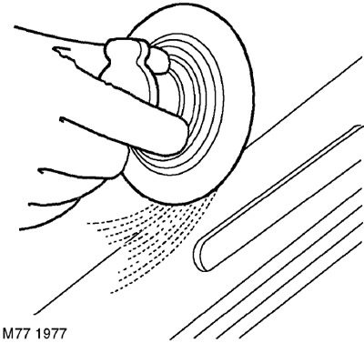


7. Always perform plug welding in inert gas if the thickness of the sheets to be welded or…


8. Clean the weld areas with a 36 grit abrasive disc or a belt sander and/or a wire brush. When cleaning, try to clean as little area as possible to preserve the galvanized metal.


This article is available at russian, bulgarian, belarusian, ukrainian, serbian, croatian, romanian, polish, slovak, hungarian
Article review: Konstantin Nazarov


Previous articles
General information about body parts repair
Replaceable body parts
General safety rules for welding

Current article
Panel replacement procedure

Next articles
Front panel assembly
Hood Lock Panel
Headlight mounting bracket
Front crossmember, lower
Front side member assembly
Front spar (front part)
Engine bay side panel assembly
Upper side of the engine compartment


Similar articles from Land Rover repair manuals:
• The structure and description of the instrument panel Discovery 3 (2004-2009)
• Panel replacement procedure Range Rover 3 (2001-2012)
• Description and operating principle of the instrument panel console Defender 2007+ (2007-2016)

Comments on this article


No comments yet


How much will 41 + 25 =


Freelander 2 
  • General information
  • Using the manual
  • Repair technique
  • Precautionary measures
  • Road test
  • Fault codes
  • Identification codes
  • Jacking and lifting
  • Maintenance - Diesel
  • Maintenance - petrol
  • Chassis
  • Suspension
  • Front suspension
  • Rear suspension
  • Wheels and tires
  • Terrain response
  • Transmission system
  • Cardan shaft
  • Rear drive axle
  • Rear axle shafts
  • Front axle shafts
  • Brake system
  • Parking brake
  • Hydraulic brake
  • Brake booster
  • Anti-lock braking system
  • Exchange rate stability
  • Steering
  • Steering column
  • Power unit
  • Engine device
  • Engine repair
  • Description of the cooling system
  • Cooling system repair
  • Fuel supply
  • Drive units
  • Launch system
  • Ignition system
  • Exhaust toxicity
  • Air filtration
  • Fuel vapor control
  • Electronic control part
  • Automatic gearbox
  • Gearbox cooling
  • Automatic transmission controls
  • Mechanical transmission
  • Transfer case
  • Exhaust system
  • Fuel tank and lines
  • Speed control
  • Electrical equipment
  • Climate control system
  • Climate control
  • Additional climate control
  • Instrument panel
  • Sound signal
  • Information and messages
  • Assistance with parking
  • Battery and alternator
  • Information and entertainment
  • Outdoor Lighting
  • Interior lighting
  • Communication network
  • Wiring harnesses
  • Anti-theft system
  • Multifunctional modules
  • Body and coating
  • Body front panels
  • Lockable body parts
  • Interior trim
  • Rear view mirrors
  • Car seats
  • Glass, frames and mechanisms
  • Instrument panel and console
  • Handles, locks, latches
  • Windshield wipers and washers
  • Sunroof
  • Bumpers
  • Seat belt system
  • Restraint system
  • Body repairs
  • Front end repairs
  • Roof element repairs
  • Side panel repairs
  • Tailgate repairs
  • Subframe and mounts

Freelander 1 
  • General information
  • Using the manual
  • Precautionary measures
  • Technique
  • Specifications
  • Connection tightening torques
  • Maintenance
  • Power unit
  • Diesel engine Td4
  • Petrol engine K1.8
  • Piston group K1.8
  • KV6 petrol engine
  • Piston group KV6
  • Decreased toxicity
  • Motor control EDC
  • Engine management MEMS
  • Motor control Siemens
  • Fuel supply diesel Td4
  • Fuel supply for K1.8 engine
  • Fuel supply of KV6 engine
  • Cooling diesel Td4
  • Engine cooling K1.8
  • Engine cooling KV6
  • Exhaust system Td4
  • Exhaust system K1.8
  • Exhaust system KV6
  • Clutch
  • Mechanical transmission
  • Transfer case
  • Automatic gearbox
  • Chassis
  • Drive shafts
  • Rear axle and final drive
  • Steering
  • Front suspension
  • Rear suspension
  • Brake system
  • Body and coating
  • Passive safety
  • Doors, locks and glass
  • Exterior body parts
  • Interior trim details
  • Seats
  • Roof hatch
  • Roof
  • Body geometry
  • Body parts repair
  • Sealing and corrosion
  • Electrical equipment
  • Heating and ventilation
  • Air conditioning
  • Windshield wipers and washers
  • Starting engine and charging
  • Lighting and headlights
  • Control modules
  • Safety system
  • Window management
  • Entertainment systems
  • Wiring harnesses
  • Governing bodies
  • Devices


LRman.ru © 2013-2026 | Mobile version | Free Lander | Discovery | Range Rover | Defender | Contacts | | Sitemap |
Car repair and service instructions Land Rover: Freelander, Discovery, Range Rover, Defender
We use cookies to make pages load faster and provide a more user-friendly experience 🍪