


Contents: Removal the panel ⇩ Preparation of old surfaces ⇩ Preparing new mating surfaces ⇩ Installation and alignment ⇩ Welding ⇩
These materials are intended to familiarize you with the basic methods of removing and replacing damaged panels. The standard method may vary slightly depending on the vehicle being repaired. The main goal of repair operations involving the removal and replacement of body panels is to ensure maximum compliance with the Land Rover factory standards.
Removal the panel
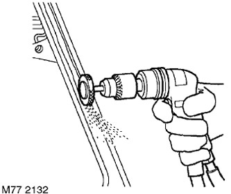
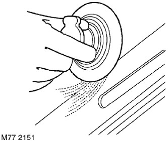
1. Expose the spot weld. For spot welds hidden under the coating, use an abrasive wheel or wire brush mounted on a pneumatic drill or a regular hand-held wire brush.
NOTE: On wheel arch surfaces, it may be necessary to soften the protective coating using a hot air gun to access the spot weld.
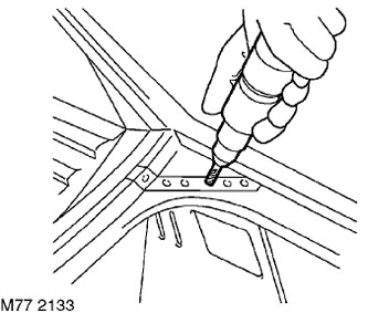
2. Drill out the weld spots using a cobalt drill.
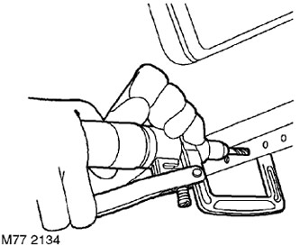
3. A clamp-type spot weld removal device can be used for this purpose.
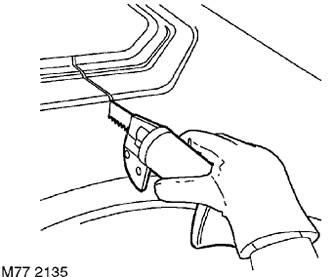
4. Cut out the damaged area of the panel using a pneumatic saw.
NOTE: On some panel joints joined by MIG welding or brazing, the weld or brazing should be removed with an abrasive tool if possible before cutting the panel.
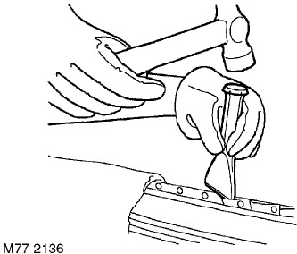
5. Disassemble the spot weld joint and remove the remaining damaged panel using a hammer, punch, chisel and pliers.
Preparation of old surfaces
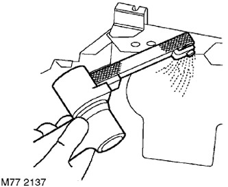
1. Clean all panel joints to a smooth metallic shine using a belt-type abrasive tool.
NOTE: Before stripping, remove any remaining sealant with a hot air gun to reduce the risk of toxic fumes from being released when the metal is heated.
Caution: This equipment should be used with caution, avoiding intense heating of parts.
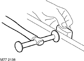
2. Straighten the joint of the old panel using a support block and a hammer.
CAUTION: Never use the same tool for working steel and aluminum. Tools for working steel should be stored separately from tools for working aluminum.
Preparing new mating surfaces
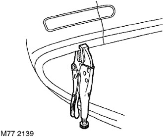
1. Mark the area of the new panel and cut it to size, leaving an allowance of approximately 50 mm to overlap the joint of the existing panel. Check that the new panel or area fits with the adjacent panels. (for example, the side panel should match the door or trunk lid). Secure the new panel with clamps.
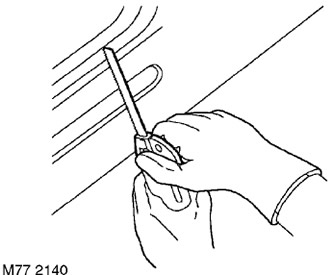
2. Trim the old and new panels to form the joint of the desired shape. Remove all clamps and remove any scrap metal.
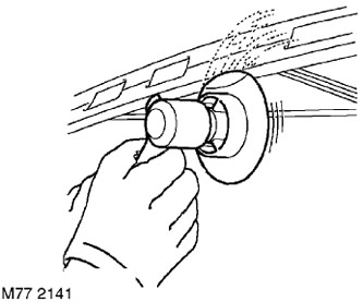
3. Prepare the edges of the joint of the new panel by cleaning them to a metallic shine. This should be done both from the outside and from the inside.
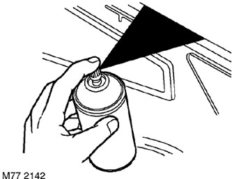
4. Apply the appropriate joint preparation compound to the weld areas using a brush or aerosol can.
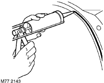
5. Apply sealing paste to the mating surfaces of the panels.
Installation and alignment
1. Place the new panel and align it with the panel to be joined. Secure the panel to be installed using special welding clamps. If an enveloping weld is required, install a clamp on the edge of the old panel or install a clamp behind the joint.
NOTE: In cases where it is difficult to secure the panel with welding clamps, tack weld the parts.
Welding
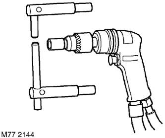
1. Select spot welding equipment and use a cutting machine to shape the ends of the electrodes. The diameter of the electrode end should be equal to twice the thickness of the sheet to be welded plus 3.0 mm.
CAUTION: Use electrodes no longer than 300 mm.
NOTE: To maintain welding efficiency, it is necessary to periodically clean and reshape the electrode tips.
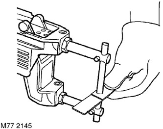
2. Install the welding brackets and test the equipment for proper operation using a piece of the material to be welded. If you do not have special testing equipment, test the strength of the weld. When applying force to separate the welded parts, the metal around the weld point should break before the weld point.
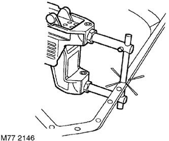
3. If access to the parts allows, use welding equipment for spot welding with resistance heating. If possible, use a welding monitor to control the quality of the weld.
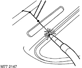
4. Tack weld the panels to be joined and, if necessary, check their fit and edge alignment. The gap between the weld spots should minimize warping. A hacksaw blade can be used for checking.
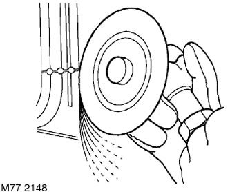
5. Clean the weld areas with a 36 grit abrasive disc or, if access is difficult, with a belt sander.
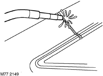
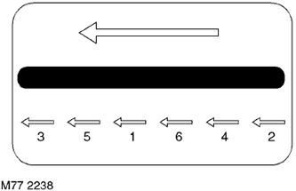
6. Jointing by intermittent welding in inert gas. When welding in inert gas, a large amount of heat is generated when the weld seam is long, which can cause warping and distortion of the panels. To avoid loss of shape, divide the seam length into small sections as shown in the figure. The arrows indicate the welding direction.
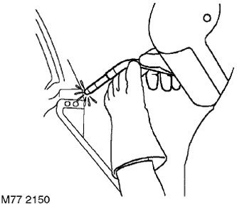
7. Always perform plug welding in inert gas if the thickness of the sheets to be welded or difficult access make spot welding impossible. Plug welding can be performed using holes left after spot welding has been drilled or through specially drilled or punched holes of approximately 8 mm in diameter.
8. Clean the weld areas with a 36 grit abrasive disc and/or a belt sander and/or a wire brush. When cleaning, try to clean as little space as possible to preserve the galvanized metal.
9. Perform all further operations to seal the joint.
REPAIR WORK, Factory processing.
Comments on this article