NOTE: The front spar is serviced as a separate welded panel. This procedure consists of installing a long section cut off from the service panel and discarding the rear section.
NOTE: The service panel is not fully welded.
NOTE: The cut should be made at least 20mm ahead of the laser weld.
Removing
1. When replacing the front side member, the following elements are removed:
- front bumper cover
- Front bumper
- Hood latch panel
- Both front fenders
- Front bumper support
- End panel, front side member
- Front reinforcing element of the fender apron panel
- Wing apron bottom panel
NOTE: It is also necessary to remove the engine and suspension as a unit.
2. For more information on this repair procedure, refer to the following sources: For more information, refer to the chapter: Body and Frame (501-26 Body Repairs - Vehicle Special Information and Approval Checks, Description and Operation) / Standard techniques used at the service station (100-00 General information, Description and principle of operation).
3. Remove the front side member end panel. For more information, see chapter: Front side member protection panel (501-27 Repairs of sheet metal elements of the front end, Removal and installation).
4. Remove the radiator cooling block. For more information, see chapter: Radiator (303-03A Engine cooling - 3.2L NA - I6, Removal and installation).
5. Remove the engine and front suspension as a single unit.
6. Release the brake line and set it aside.
7. Left side: Loosen the battery electrical junction box and place it aside.
8. Left side: Remove the air intake duct.
9. Left side: Release the brake pipe on the side member and set it aside.
10. Left side: Remove the anti-lock brake system module (ABS). For more information, refer to the chapter: Anti-Lock Braking System Module (ABS) (206-09A Anti-lock braking system, Removal and installation).
11. Right side: Remove the windshield washer reservoir. For more information, see chapter: Windshield washer reservoir (501-16 Windshield wipers and washers, Removal and installation).
12. Right side: Remove the motor support bracket. For more information, see chapter: Right Engine Mount (303-01B Engine - 2.2L Duratorq - Td4, Removal and installation).
13. Right side: Remove the brake pipes on the fender apron.
14. Right side: Remove the fender apron A/C line.
15. Loosen and set aside the insulating material located on the baffle.
16. Release the wiring harness and set it aside.
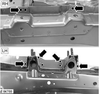
17. Mill out the contact welding points.
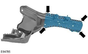
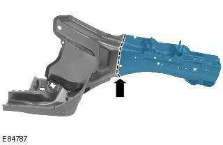
18. Cut off the old panel at the location shown. The cut should be made at least 20 mm ahead of the laser weld.

19. Separate the connections and remove the old panel.
Installation
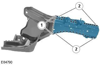
1. Cut a new section from the service panel.
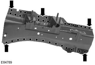
2. Prepare a new panel in the areas shown where it is not fully welded and MIG weld with electric rivets.
3. Prepare the mating surfaces of the old and new panels.
4. Drill holes in the new panel in preparation for MIG electric rivet welding.
5. Position the new panel in the desired location and secure it. Check position alignment. If it is correct, go to the next paragraph. If not, make any necessary adjustments and recheck before continuing.
6. After fixing the panels:
- 1. Make tack welds for the butt joint.
- 2. Weld with electric rivets using MIG technology.
7. Clean the tack welds.
8. Make a MIG butt weld.

9. Clean all welds.
10. Installation of the corresponding panels and mechanical elements is carried out in the reverse order of removal.
Comments on this article