Contents: Ignition/no charge indicator light ⇩ Low oil pressure warning light ⇩ Engine Malfunction Indicator Light ⇩ Seat belt warning light ⇩ Additional restraint system…⇩ Left and right turn signal indicator…⇩ Brake system warning light ⇩ High Engine Coolant Temperature…⇩ High beam indicator lamp ⇩ Tire pressure monitoring system…⇩ Anti-lock brake system warning light ⇩ Low fuel level warning indicator…⇩ Parking brake warning light ⇩ Rear fog light indicator lamp ⇩ Fog light indicator lamp ⇩ Adaptive front lighting indicator…⇩ Speed control system indicator light ⇩ Trailer warning light ⇩ Low washer fluid level indicator…⇩ Low Engine Coolant Level Warning…⇩ Gearbox warning light ⇩ Hill Descent Control (HDC) indicator…⇩ Door open indicator light ⇩ Engine Management System Warning…⇩ Side light indicator lamp ⇩ Dynamic Stability Control System…⇩ Controlled descent system activation…⇩ Anti-theft alarm indicator ⇩ Glow plug indicator light ⇩ Overspeed warning light ⇩ Vehicles equipped with the system…⇩
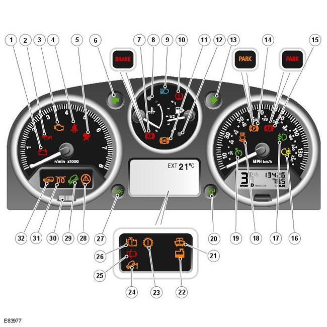
| Pos. | Spare part number | Name |
| 1 | - | Ignition/no charge indicator light |
| 2 | - | Low Oil Pressure Warning Light |
| 3 | - | Malfunction Indicator Lamp (MIL) (Gasoline Models Only) |
| 4 | - | Seat belt warning light |
| 5 | - | Supplemental Restraint System (SRS) Warning Light |
| 6 | - | Left turn signal indicator lamp |
| 7 | - | Brake warning light (low brake fluid/Emergency Brake Assist (EBA)/Electronic Brakeforce Distribution (EBD)) |
| 8 | - | High Engine Coolant Temperature (ECT) Warning Light |
| 9 | - | High beam indicator lamp |
| 10 | - | Tire Pressure Monitoring System (TPMS) Warning Light |
| 11 | - | Anti-lock Brake System (ABS) Warning Light |
| 12 | - | Low Fuel Warning Light |
| 13 | - | Right turn signal indicator lamp |
| 14 | - | Parking brake indicator lamp - not used |
| 15 | - | Parking brake warning light |
| 16 | - | Rear fog light indicator light |
| 17 | - | Front fog light indicator light |
| 18 | - | Adaptive Front Lighting System (AFS) indicator light |
| 19 | - | Cruise control indicator light |
| 20 | - | Trailer warning light |
| 21 | - | Low washer fluid level indicator light (Low series variants only) |
| 22 | - | Low Coolant Level Warning Light (Low Series Variants Only) |
| 23 | - | Gearbox Warning Light (Low Series Variants Only) |
| 24 | - | Hill Descent Control (HDC) Malfunction Indicator Lamp (Low Series Variants Only) |
| 25 | - | Door open indicator light (Low series variants only) |
| 26 | - | Engine Management System Warning Light (Low Series Variants Only) |
| 27 | - | Side light indicator lamp |
| 28 | - | Dynamic Stability Control (DSC) Warning Light |
| 29 | - | HDC On Indicator Light |
| 30 | - | Anti-theft alarm indicator |
| 31 | - | Glow Plug Indicator Light (Diesel Models Only) |
| 32 | - | Fuel fired auxiliary heater indicator light (if equipped) |
The "low series" instrument cluster contains 39 warning lights and indicators, while the "high series" instrument cluster contains 27. The warning lights on the "high series" instrument clusters are supplemented by messages displayed in the message center. For more information, refer to the chapter: Information and Message Center (413-08 Information and Message Center, Description and Function).
The indicator lamps can be divided into two groups: those controlled by the instrument cluster electronic unit and those controlled by control modules of other vehicle systems. Indicator lamps and indicators controlled by the instrument cluster are activated in accordance with its own software. Externally controlled indicator lamps and indicators are powered by the corresponding control module of another system or are switched on by the instrument cluster when a message is received from the CJB on the medium speed CAN bus.
Ignition/no charge indicator light
The ignition/charge indicator lamp is controlled by the instrument cluster software and illuminates when signals are received on the medium speed CAN bus from the ECM via the CJB. This lamp illuminates red when the vehicle enters power mode 6 and extinguishes when the engine is started.
If the indicator lamp does not go out after starting the engine or lights up while the vehicle is moving, this means that due to a malfunction, the battery is not being recharged by the generator.
Low oil pressure warning light
The low oil pressure indicator lamp is illuminated by the instrument cluster when signals are received on the medium speed CAN bus from the CJB. The signal is initiated in the ECM and is generated by the engine oil level sensor on petrol vehicles and the engine oil pressure sensor on diesel vehicles.
This lamp illuminates red when the vehicle enters power mode 6 and remains illuminated for a 3-second bulb check. If the lamp remains illuminated while the engine is running, the engine should be stopped immediately at the next safe opportunity.
Engine Malfunction Indicator Light
The Malfunction Indicator Lamp (MIL) is illuminated by the instrument cluster when signals are received on the medium speed CAN bus from the CJB. The signal is initiated in the ECM and is generated if a malfunction of the on-board diagnostic (OBD) system is detected that causes elevated levels of harmful emissions. The cause may be a malfunction of the engine management system or transmission.
The MIL illuminates in amber when the vehicle enters power mode 6 and remains illuminated for a 3 second bulb check. The bulb check is now performed by the ECM via the CJB rather than the instrument cluster. If the MIL is subsequently illuminated, a vehicle inquiry should be performed using the Land Rover approved diagnostic system at the earliest opportunity.
Seat belt warning light
The seat belt indicator lamp illuminates red when signals are received on the medium speed CAN bus from the CJB. The signal is initiated in the restraint control module (RCM), which monitors the status of the occupant classification system and the switches located in the seat belt buckles.
Depending on the vehicle configuration, three warning options are offered:
- Reminder (all vehicles except North American (NAS))
- Federal Motor Vehicle Safety Standard (FMVSS) 208 Reminder (NAS Vehicles Only)
- Seat belt status reminder
The conditions for switching on the seat belt indicator lamp are as follows:
- Reminder
- Car in power mode 6
- The driver's seat belt is not locked into the buckle
- Oversized passenger registered in front passenger seat with seat belt unfastened
The indicator lamp remains on until either the ignition is switched off or conditions 2 and 3 no longer exist.
- FMVSS-208 Reminder
- Car in power mode 6
- The driver's seat belt is not locked into the buckle
The indicator lamp will remain on for 65 seconds and will be accompanied by a single 6-second sound signal coming from the instrument cluster speaker.
NOTE: The indicator lamp and buzzer will not activate if these conditions occur 75 seconds after the vehicle enters power mode 6.
The indicator lamp will go out and the buzzer will stop sounding when the ignition is switched off or the driver's seat belt is fastened.
- Seat belt status reminder
- Vehicle in Power Mode 6 (all vehicles except NAS vehicles)
- Vehicle in power mode 6 for 75 seconds (NAS vehicles only)
- The speed of the car is more than 10 km/h
- The driver's seat belt is not locked into the buckle
- Oversized passenger registered in front passenger seat with seat belt unfastened
The indicator lamp will flash at a rate of 2 Hz accompanied by an audible signal from the instrument cluster for 10 seconds. This will be followed by a 10-second period in which the indicator lamp is constantly illuminated and there is no audible signal. This 10-second cycle will be repeated for a maximum of 190 seconds or if any of the conditions listed above cease to exist.
Additional restraint system indicator light
The Supplemental Restraint System (SRS) indicator lamp illuminates when a signal is received on the medium speed CAN bus from the CJB. The signal is initiated in the RCM, which monitors the SRS status and illuminates the red indicator lamp in the appropriate mode.
The SRS indicator lamp is illuminated by the RCM for a 6 second bulb check period when the vehicle first enters power mode 6. If a malfunction is detected in the indicator lamp, the instrument cluster returns a signal via the medium speed CAN bus via the CJB to the RCM and a diagnostic trouble code (DTC) is stored in the RCM memory. In addition, the odometer display will show the message 'SrS'. For further information, refer to: Information and Message Centre (413-08 Information and Message Centre, Description and Operation).
Left and right turn signal indicator lamps
The green left and right turn signal indicators are illuminated when signals are received on the medium speed CAN bus from the CJB. The CJB provides a CAN bus signal with one of the following values:
- 0 - Left multifunction switch on the steering column in the central position
- 1 - The left multifunction switch on the steering column is turned to the left
- 2 - The left multifunction switch on the steering column is turned to the right
- 3 – Hazard warning lights requested
When the vehicle is in power mode 6, the instrument cluster will initiate flashing of the corresponding turn signal indicator lamp if a medium speed CAN bus signal with a value of 1 or 2 is received. Medium speed CAN bus signals with a value of 3 will activate simultaneous illumination of the left and right turn signal indicator lamps regardless of power mode.
After the left and right turn signal indicator lights are activated, the instrument cluster speaker will make a ticking sound.
Brake system warning light
EBA and EBD warnings are transmitted to the CJB from the ABS module via the high speed CAN bus. These signals are transmitted to the instrument cluster via the medium speed CAN bus and will activate the brake warning lamp when the vehicle is in power mode 6. If an EBA warning is requested, the lamp will illuminate in amber. If an EBD warning is requested, the lamp will illuminate in red.
Low brake fluid warnings are also transmitted to the instrument cluster from the CJB via the medium speed CAN bus. The signal is initiated in the ABS module, which receives a hardwired input signal from the brake fluid level sensor. If a low brake fluid warning is requested, the indicator lamp will illuminate red when the vehicle is in power mode 6.
The brake system indicator lamp will also turn on for a 3-second bulb check period when the vehicle first enters power mode 6. The indicator lamp will glow yellow for 1.5 seconds and then red for 1.5 seconds.
High Engine Coolant Temperature Warning Light
The red high engine coolant temperature (ECT) indicator light is controlled by the engine temperature gauge software (see above).
High beam indicator lamp
The high beam indicator lamp is illuminated when a medium speed CAN bus signal is received from the CJB. The signal is initiated in the light switch module and transmitted to the CJB via the LIN bus. The instrument cluster only illuminates the high beam indicator lamp when the vehicle is in power mode 6 and the left multifunction switch on the steering column is moved to the high beam position.
Tire pressure monitoring system warning light
The tire pressure monitoring system (TPMS) indicator lamp is controlled by the instrument cluster when receiving signals on the medium speed CAN bus from the CJB. The signal is initiated by the TPMS module. The indicator lamp illuminates in amber for a 3-second bulb check period when commanded by the TPMS module when the vehicle enters power mode 6. If the indicator lamp does not go out or flashes after starting the engine or while driving, this indicates that a fault has occurred in the TPMS system. The tire pressure must be monitored manually until the fault is corrected. For more information, refer to the chapter: Wheels and tires (204-04 Wheels and tires, Description and operation).
Anti-lock brake system warning light
The Anti-lock Brake System (ABS) indicator lamp is controlled by the ABS module, which transmits a message via the high-speed CAN bus to the CJB. The CJB transmits a message to the instrument cluster via the medium-speed CAN bus. The indicator lamp illuminates in amber for a 3-second bulb check as commanded by the ABS module when the vehicle enters power mode 6. If the indicator lamp remains illuminated after the engine has been started or illuminates while driving, the ABS system has a fault and its operation is cancelled.
If during the bulb check the indicator lamp comes on for 0.5 seconds, then goes off for 0.5 seconds, and then remains on for two seconds of the bulb check, this indicates that there are fault codes in the ABS module memory.
If the warning lamp was illuminated due to a wheel speed sensor malfunction, the warning lamp remains illuminated in the next ignition cycle even if the malfunction is corrected. After the vehicle accelerates to a speed exceeding 20 km/h (12 mph), the warning lamp turns off. This procedure allows the ABS module to perform a complete system check to ensure that the correct signal is being output from the replaced sensor.
Low fuel level warning indicator light
The low fuel warning indicator is controlled by the fuel gauge software (see above). When the vehicle enters power mode 6, the low fuel warning indicator illuminates amber during a 3-second bulb check. If the fuel gauge software determines that the low fuel warning indicator should be turned on, it initiates a 2 Hz flash of the indicator for 5 seconds. The first flash is accompanied by an audible signal from the instrument cluster. After the 5-second flashing period, the indicator remains on until fuel is added to the tank or the vehicle ignition is turned off.
Parking brake warning light
The red parking brake indicator lamp illuminates when a signal is received on the medium speed CAN bus from the CJB. The signal is initiated in the parking brake microswitch which is hardwired to the CJB. The parking brake indicator lamp will only illuminate when the parking brake is applied and the vehicle is in power mode 6.
Rear fog light indicator lamp
The rear fog lamp indicator is illuminated when a medium speed CAN bus signal is received from the CJB. The indicator illuminates in amber when the vehicle is in power mode 6 and rear fog lamp operation has been requested.
Fog light indicator lamp
The fog lamp indicator lamp is illuminated when a medium speed CAN bus signal is received from the CJB. The indicator lamp illuminates green when the vehicle is in power mode 6 and fog lamp operation has been requested.
Adaptive front lighting indicator lamp
The Adaptive Front Lighting System (AFS) indicator lamp is controlled by the AFS module. The AFS module is hardwired to the CJB, which transmits signals to the instrument cluster via the medium speed CAN bus. When the vehicle enters power mode 6, the AFS indicator lamp illuminates amber for a 3-second bulb check. If a fault is detected during AFS operation, the AFS indicator lamp flashes at a rate of 2 Hz.
Speed control system indicator light
The speed control indicator lamp is controlled by the ECM which transmits a speed control activation signal to the instrument cluster via the CJB. The indicator lamp will illuminate in amber when the vehicle is in power mode 6 and speed control is active.
Trailer warning light
The trailer indicator lamp is controlled by the instrument cluster when receiving signals from the CJB via the medium speed CAN bus. When the trailer wiring is connected to the vehicle electrical system and the direction indicator switch is activated, the CJB sends a signal to the instrument cluster to illuminate the trailer indicator lamp. The instrument cluster software sets the flashing frequency of the green indicator lamp. The trailer indicator lamp flashes slowly, at the same rate as the direction indicator lamps.
Low washer fluid level indicator light
The low washer fluid level indicator is illuminated when a signal is received on the medium speed CAN bus from the CJB. The signal is initiated in the low washer fluid level switch, which is hardwired to the CJB.
The amber low washer fluid indicator comes on for a 3-second bulb check period when the vehicle enters power mode 6. If a low washer fluid level is detected for more than 15 seconds while the vehicle is in power mode 6, the instrument cluster turns on the indicator.
Low Engine Coolant Level Warning Light
The low engine coolant level indicator lamp illuminates when a medium speed CAN bus signal is received from the CJB while the vehicle is in power mode 6. The signal is initiated in the ECM, which transmits the signal to the CJB via the high speed CAN bus.
When the vehicle enters power mode 6, the yellow Low Engine Coolant indicator light comes on for a 3-second bulb check period. If the light remains on after this period, the cooling system should be checked for leaks and coolant should be added as needed.
Gearbox warning light
The transmission warning lamp displays warnings for the automatic transmission and active clutch. The lamp illuminates when signals are received on the medium speed CAN bus from the CJB. The signals are initiated in the transmission control module (TCM) and the active clutch control module respectively and are transmitted to the CJB on the high speed CAN bus.
The transmission indicator lamp is a two-color indicator lamp that comes on for a 3-second bulb check period when the vehicle enters power mode 6. During the first 1.5 seconds of the bulb check, the indicator lamp illuminates amber, after which it illuminates red for 1.5 seconds.
The table below details the indicator lamp colours in relation to the messages provided by the message centre.
| Message in the message center | Indicator lamp color | |
| Warning regarding automatic transmission | Warning regarding active clutch | |
| TRANSMISSION FAULT | Yellow | Red |
| TRANSMISSION FAULT AND OVERHEATING | Red | Absent. |
| TRANSMISSION FAULT LIMITED GEARS AVAILABLE | Red | Absent. |
| TRANSMISSION FAULT TRACTION REDUCED | Absent. | Red |
| TRANSMISSION OVERHEAT SLOW DOWN | Yellow | Red |
Hill Descent Control (HDC) indicator light
The amber Hill Descent Control (HDC) indicator lamp illuminates when signals are received on the medium speed CAN bus from the CJB. The signals are initiated in the ABS module and transmitted to the CJB via the high speed CAN bus.
When the vehicle enters power mode 6, the HDC indicator lamp will illuminate for a 3-second bulb check period. If the HDC indicator lamp illuminates during HDC operation, this indicates that a "reduce efficiency" strategy has been entered due to a component failure.
If the HDC indicator lamp flashes, this indicates that the "efficiency reduction" strategy has been activated due to overheating of the brake system. In this case, the first flash is accompanied by an audible signal from the instrument cluster and the green HDC activation indicator lamp goes out. For further information, refer to the chapter: Anti-lock Brake System - Stability Assist Function (206-09C Anti-lock Brake System - Stability Assist Function, Description and Function).
Door open indicator light
The door open indicator is illuminated when signals are received on the medium speed CAN bus from the CJB. The signals are initiated in the door modules which are hardwired to the CJB. The door open indicator will illuminate red if the CJB receives a door open signal from any door module when the vehicle is in power mode 6.
Engine Management System Warning Light
The engine management system indicator lamp illuminates when signals are received on the medium speed CAN bus from the CJB. The signals are initiated in the ECM and transmitted to the CJB on the high speed CAN bus.
The amber Engine Management System indicator lamp illuminates for a 3 second bulb check period when the vehicle enters power mode 6. If the indicator lamp then illuminates, a DTC will be stored in the ECM which must be interrogated using the Land Rover approved diagnostic system to retrieve it.
Side light indicator lamp
The green parking lamp indicator lamp is illuminated when a medium speed CAN bus signal is received from the CJB. The signal is initiated in the light switch module and transmitted to the CJB via the LIN bus. The instrument cluster will only illuminate the parking lamp indicator lamp when the vehicle is in power mode 6.
Dynamic Stability Control System Indicator Lamp
The Dynamic Stability Control (DSC) indicator lamp is illuminated by the instrument cluster when signals are received on the medium speed CAN bus from the CJB. The signal is initiated by the ABS module. The amber engine management indicator lamp is illuminated for a 3 second bulb check when the vehicle enters power mode 6. If no faults are present, the indicator lamp goes out when the check is complete.
When the DSC system is activated, the indicator lamp starts flashing, informing the driver that the system is regulating the engine power output and the braking force applied to the wheels. If the indicator lamp remains on after the engine has been started or illuminates while driving, the DSC system is faulty or has been deactivated by the driver using the switch on the instrument panel.
Controlled descent system activation indicator light
The Hill Descent Control indicator is illuminated by the instrument cluster when signals are received on the medium speed CAN bus from the CJB. The signal is initiated by the ABS module. The indicator illuminates green when the HDC system is active and the vehicle speed is below a preset value. If the vehicle speed is above the preset value, the HDC indicator will flash until the vehicle speed is reduced. On high-series instrument clusters, a message will be displayed in the message centre. For further information, refer to:
Anti-lock Braking System - Directional Stability Assist Function (206-09C Anti-lock Braking System - Directional Stability Assist Function, Description and Operation), Information and Message Center (413-08 Information and Message Center, Description and Operation).
If the temperature of the brake discs exceeds a preset value during HDC operation, the system initiates a brake fade strategy. During the brake fade, the HDC indicator lamp flashes and a corresponding message appears in the message center display in the high-series instrument cluster. Once the discs have cooled to an acceptable temperature, HDC is reactivated and the indicator lamp lights up continuously.
Anti-theft alarm indicator
The anti-theft alarm indicator is controlled directly from the CJB via wires. There is no software functionality provided in the instrument cluster to control the anti-theft alarm indicator.
The article is based on information from the website: lrman.ru
For more information, refer to the chapter: Anti-theft system - active (419-01A Anti-theft system - active, Description and operating principle).
Glow plug indicator light
The glow plug indicator lamp is illuminated upon receipt of a medium speed CAN bus signal from the CJB. The signal is initiated by the diesel ECM and indicates that the glow plugs are operational. The indicator lamp will illuminate in amber when the vehicle enters power mode 6 and a glow plug activation signal is received from the ECM. When the combustion preheating procedure is completed, the ECM commands the instrument cluster to turn off the glow plug indicator lamp. For additional information, refer to: Electronic Engine Controls - 2.2L Diesel (303-14 Electronic Engine Controls - 2.2L Diesel, Description and Operation).
Overspeed warning light
The amber overspeed indicator lamp is illuminated when a signal is received on the medium speed CAN bus from the CJB when the vehicle is in power mode 6. The vehicle speed signal is initiated in the ABS module. This signal is also used by the speedometer (see above).
The instrument cluster causes the overspeed warning lamp to flash at a frequency of 2 Hz for 5 seconds if the speed exceeds 120 km/h (75 mph). The first flash of the warning lamp is accompanied by an audible signal from the instrument cluster. If the vehicle speed is at this level, the warning lamp remains on after the 5-second flashing period. The instrument cluster will switch off the warning lamp if the vehicle speed drops below 114 km/h (75 mph).
Vehicles equipped with the system "Stop/Start"
Economy mode indicator "Stop/Start":
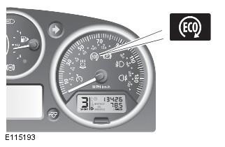
The TD4_e features Land Rover's first intelligent Stop/Start system. The system automatically switches off and restarts the vehicle's engine when certain conditions are met. This reduces the time the engine spends idling, reducing fuel consumption and emissions. When the engine is switched off, the Eco icon in the instrument cluster illuminates. Other warning lights normally associated with engine shutdown (such as the ignition and low oil pressure lights) are disabled so that they do not illuminate when the engine is switched off in Stop/Start mode.
For further information, please refer to the chapter: Starting system (303-06C Starting system - 2.2L Duratorq - Td4, Vehicles manufactured from 03/2009, Description and operation).
Eco Switch:
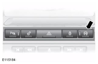
The Stop/Start system is automatically activated when the ignition is switched on. However, the driver can deactivate the system by pressing the Eco button on the control panel. For more information, refer to the chapter: Starting system (303-06C Starting system - 2.2L Duratorq - Td4, Vehicles manufactured from 03/2009, Description and operation).
The Eco button also controls the gear shift indicator; for more information, see the Gear Shift Indicator section below.
Comments on this article