car logo Ford
car logo Volkswagen
car logo BMW
car logo Opel
car logo Audi
car logo Toyota
car logo Peugeot
English Русский
Български
Беларускі
Український
Српски
Hrvatski
Română
Polski
Slovenský
Magyar


Main
Freelander
Discovery
Range Rover
Defender
Contacts
Articles

Draining the liquid and filling the cooling system with vacuum (Freelander 2)

 
  • Main
  • Freelander
  • Freelander 2
  • Power unit
  • Cooling system repair
  • Draining the liquid and filling the cooling system with vacuum
 
        0  
WARNING: To avoid being scalded by hot coolant or steam, use extreme caution when removing the coolant expansion tank pressure cap when the cooling system is hot. Allow the engine to cool, then wrap a thick cloth around the coolant expansion tank cap and slowly loosen it until the pressure release process begins. Step back while the cooling system releases pressure. After ensuring that all pressure has been released, and without removing the cloth, twist and remove the coolant expansion tank pressure cap. Failure to follow these instructions could result in personal injury.


To prevent corrosion and engine damage from freezing coolant, the engine cooling system must be filled with the correct grade of antifreeze in the correct concentration. Failure to do so may result in damage to the vehicle.


Coolant can damage paintwork. If you spill coolant, clean it up immediately and rinse the area with water.


1. Set the heater controls to maximum heat (HOT).

2. Unscrew the expansion tank cap.

WARNING: Never remove the coolant expansion tank cap when the system is hot, as steam or coolant escaping from the cap could cause serious injury, such as scalding.
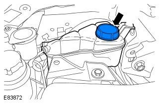

WARNING: Never remove the coolant expansion tank cap when the system is hot, as steam or coolant…


3. Raise the vehicle and place it on supports.


WARNING: Do not work on or under a vehicle supported solely by a jack. Always support the vehicle securely.


4. Remove the engine guard. Refer to procedure: Engine Guard (501-02 Front Body Panels, Removal and Installation).

5. Remove the right front mudguard.

NOTE: Wheel shown removed for clarity.


6. Place a container to collect the liquid.

7. Connect the hose to the radiator drain cock.
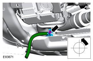
7. Connect the hose to the radiator drain cock.


8. Open the radiator drain cock.

9. Drain the coolant from the radiator.

10. Remove the drain plug.
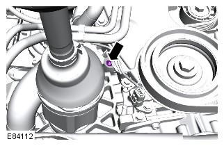
10. Remove the drain plug.


11. Drain the coolant from the engine.

12. Close the radiator drain cock and remove the hose.

13. Screw in the drain plug. Tightening torque: 23 Nm

14. Prepare a sufficient amount of coolant of the required concentration.

15. Install the cooling system vacuum filler adapter onto the expansion tank.
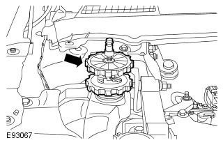


15. Install the cooling system vacuum filler adapter onto the expansion tank.


16. Install the vacuum filling device measuring device onto the cooling system filling adapter.
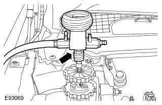
16. Install the vacuum filling device measuring device onto the cooling system filling adapter.


17. Install the venturi tube assembly onto the vacuum filling instrument measuring device.
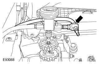
17. Install the venturi tube assembly onto the vacuum filling instrument measuring device.


18. Connect the regulated compressed air supply line to the venturi tube assembly.
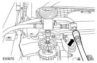
18. Connect the regulated compressed air supply line to the venturi tube assembly.


19. Place the coolant pickup tube in a container of clean coolant.


NOTE: Make sure no air gets into the hose.


20. Place the air extraction hose into the container.

21. Open the air supply valve.

NOTE: Make sure the coolant supply valve on the vacuum filler gauge is in the closed position.


NOTE: The coolant filling vacuum tool requires an air pressure of 6 to 8 bar to operate properly.


NOTE: Small diameter or long air lines may restrict air flow to the coolant filler vacuum tool.
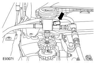

NOTE: Small diameter or long air lines may restrict air flow to the coolant filler vacuum tool.


22. Open the coolant supply valve for 2 seconds to fill the coolant supply hose.
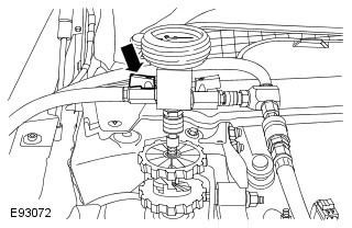
22. Open the coolant supply valve for 2 seconds to fill the coolant supply hose.


23. Gradually apply air pressure until the needle on the vacuum filling device gauge reaches the green segment.

24. Close the air supply valve.

24. Close the air supply valve.


25. Wait 1 minute to ensure the vacuum is held.
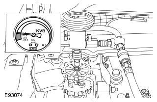


25. Wait 1 minute to ensure the vacuum is held.


26. Disconnect the compressed air supply line.

27. Open the coolant supply valve to fill the system with coolant.

NOTE: When the coolant reaches the upper (MAX) mark on the expansion tank or the coolant stops flowing, close the coolant supply valve.
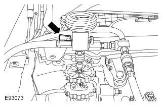

NOTE: When the coolant reaches the upper (MAX) mark on the expansion tank or the coolant stops…


28. Remove the vacuum filler gauge and the cooling system filler adapter assembly.

29. Connect the exhaust hoses to the rear exhaust pipes.

30. Start the engine and let it run.

31. Install the coolant expansion tank cap.

32. Maintain the engine speed at 2000 rpm until warm air comes out of the heater.

33. Turn off the engine and allow it to cool.

34. If coolant gets on your car, wipe it off.

35. Check the coolant level and top up if necessary.

CAUTION: Because leaking steam or coolant can cause burns, allow the vehicle's cooling system to cool before performing this procedure.


36. Install the right front mudguard.

37. Install the engine guard. Refer to procedure: Engine Guard (501-02 Front Body Panels, Removal and Installation).


This article is available at russian, bulgarian, belarusian, ukrainian, serbian, croatian, romanian, polish, slovak, hungarian
Article review: Roman Mitrofanov


Previous articles
Inspection and testing of the cooling system
Table of signs of malfunction
DTC Trouble Code Index
Pinpoint tests
Checking the cooling system elements
Draining/filling coolant and removing air

Current article
Draining the liquid and filling the cooling system with vacuum

Next articles
Removal and installation the thermostat
Coolant pump
Removal and installation the radiator
Cooling system fan
Expansion tank of the cooling system
Engine coolant level sensor


Similar articles from Land Rover repair manuals:
• Draining liquid and filling with vacuum 4.0L Discovery 3 (2004-2009)
• Cooling system (Mpi engine) Discovery 1 (1989-1998)
• Draining the coolant, flushing the system and filling Range Rover 3 (2001-2012)
• Draining the liquid and filling the cooling system with vacuum Defender 2007+ (2007-2016)

Comments on this article


No comments yet


How much will 36 + 38 =


Freelander 2 
  • General information
  • Using the manual
  • Repair technique
  • Precautionary measures
  • Road test
  • Fault codes
  • Identification codes
  • Jacking and lifting
  • Maintenance - Diesel
  • Maintenance - petrol
  • Chassis
  • Suspension
  • Front suspension
  • Rear suspension
  • Wheels and tires
  • Terrain response
  • Transmission system
  • Cardan shaft
  • Rear drive axle
  • Rear axle shafts
  • Front axle shafts
  • Brake system
  • Parking brake
  • Hydraulic brake
  • Brake booster
  • Anti-lock braking system
  • Exchange rate stability
  • Steering
  • Steering column
  • Power unit
  • Engine device
  • Engine repair
  • Description of the cooling system
  • Cooling system repair
  • Fuel supply
  • Drive units
  • Launch system
  • Ignition system
  • Exhaust toxicity
  • Air filtration
  • Fuel vapor control
  • Electronic control part
  • Automatic gearbox
  • Gearbox cooling
  • Automatic transmission controls
  • Mechanical transmission
  • Transfer case
  • Exhaust system
  • Fuel tank and lines
  • Speed control
  • Electrical equipment
  • Climate control system
  • Climate control
  • Additional climate control
  • Instrument panel
  • Sound signal
  • Information and messages
  • Assistance with parking
  • Battery and alternator
  • Information and entertainment
  • Outdoor Lighting
  • Interior lighting
  • Communication network
  • Wiring harnesses
  • Anti-theft system
  • Multifunctional modules
  • Body and coating
  • Body front panels
  • Lockable body parts
  • Interior trim
  • Rear view mirrors
  • Car seats
  • Glass, frames and mechanisms
  • Instrument panel and console
  • Handles, locks, latches
  • Windshield wipers and washers
  • Sunroof
  • Bumpers
  • Seat belt system
  • Restraint system
  • Body repairs
  • Front end repairs
  • Roof element repairs
  • Side panel repairs
  • Tailgate repairs
  • Subframe and mounts

Freelander 1 
  • General information
  • Using the manual
  • Precautionary measures
  • Technique
  • Specifications
  • Connection tightening torques
  • Maintenance
  • Power unit
  • Diesel engine Td4
  • Petrol engine K1.8
  • Piston group K1.8
  • KV6 petrol engine
  • Piston group KV6
  • Decreased toxicity
  • Motor control EDC
  • Engine management MEMS
  • Motor control Siemens
  • Fuel supply diesel Td4
  • Fuel supply for K1.8 engine
  • Fuel supply of KV6 engine
  • Cooling diesel Td4
  • Engine cooling K1.8
  • Engine cooling KV6
  • Exhaust system Td4
  • Exhaust system K1.8
  • Exhaust system KV6
  • Clutch
  • Mechanical transmission
  • Transfer case
  • Automatic gearbox
  • Chassis
  • Drive shafts
  • Rear axle and final drive
  • Steering
  • Front suspension
  • Rear suspension
  • Brake system
  • Body and coating
  • Passive safety
  • Doors, locks and glass
  • Exterior body parts
  • Interior trim details
  • Seats
  • Roof hatch
  • Roof
  • Body geometry
  • Body parts repair
  • Sealing and corrosion
  • Electrical equipment
  • Heating and ventilation
  • Air conditioning
  • Windshield wipers and washers
  • Starting engine and charging
  • Lighting and headlights
  • Control modules
  • Safety system
  • Window management
  • Entertainment systems
  • Wiring harnesses
  • Governing bodies
  • Devices


LRman.ru © 2013-2026 | Mobile version | Free Lander | Discovery | Range Rover | Defender | Contacts | | Sitemap |
Car repair and service instructions Land Rover: Freelander, Discovery, Range Rover, Defender
We use cookies to make pages load faster and provide a more user-friendly experience 🍪