car logo Ford
car logo Volkswagen
car logo BMW
car logo Opel
car logo Audi
car logo Toyota
car logo Peugeot
English Русский
Български
Беларускі
Український
Српски
Hrvatski
Română
Polski
Slovenský
Magyar


Main
Freelander
Discovery
Range Rover
Defender
Contacts
Articles

Glow plug system (Freelander 2)

 
  • Main
  • Freelander
  • Freelander 2
  • Power unit
  • Ignition system
  • Glow plug system
 
        0  
Contents: Tightening torque specifications ⇩ Description and principle of…⇩ Job ⇩

Tightening torque specifications


DescriptionНмpound-foot
Glow plugs107

Description and principle of operation
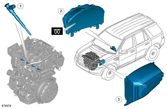

Description and principle of operation


Pos.Spare part numberName
1-Glow plugs
2-Glow Plug Indicator Light
3-BJB

Glow plugs are installed on the intake side of each cylinder; they serve to warm up the combustion chambers before and during cranking. This facilitates cold starting, reduces the level of exhaust toxicity and engine noise when the cold engine is idling.

The wiring harness on each row of glow plugs is connected to a separate relay and fuse link in the BJB (battery junction box). Each glow plug is grounded through a mounting on the cylinder head. The glow plug relay is controlled by the ECM, which also controls the glow plug indicator light in the instrument cluster.

Each glow plug is a tubular heating element with a spiral filament that is encased in powdered magnesium oxide. The tip of the tubular heating element contains a heating coil. Behind the heating coil is a control coil connected in series. The control coil regulates the current supplied to the heating coil, providing protection against overheating.


Job


There are three phases of glow plug operation: Pre-glow, Cranking Glow, and Post-glow. The ECM determines the glow time based on the ECT (Engine Coolant Temperature) signal. The lower the engine coolant temperature, the longer the glow time.

[The original article is located on: www.lrman.ru]

When the ignition switch is turned to position II, the ECM calculates any required preheat time and, if preheat is required, energizes the glow plug relay in the BJB. When a preheating requirement exists, the ECM sends a message over the high speed CAN bus to the instrument cluster to request that the glow plug indicator lamp be illuminated. The glow plug indicator lamp remains illuminated until the end of phase one or until the key is turned to the crank position, whichever comes first. If required, the ECM leaves the glow plug relay on during cranking and for a specified time after the engine has started.

The ECM monitors the glow plug relay power and control circuit for proper operation, continuity, short circuit, and open circuit. If a malfunction is detected, the ECM stores a corresponding DTC and keeps the glow plug indicator lamp on continuously when the ignition switch is in position II.


This article is available at russian, bulgarian, belarusian, ukrainian, serbian, croatian, romanian, polish, slovak, hungarian
Article review: Roman Mitrofanov


Previous articles
Engine Ignition System Specifications
Description and operating principle of the ignition system
Ignition system control diagram
Inspection and testing of the ignition system
Table of signs of malfunction
DTC Trouble Code Index
Ignition coil in block with spark plug
Spark plugs

Current article
Glow plug system

Next articles
Glow Plug Control Circuit
Inspection and testing of glow plugs
Glow Plug DTC Indicator
Pre-heating plugs


Similar articles from Land Rover repair manuals:
• Glow Plug Relay Discovery 3 (2004-2009)
• Glow plug relay Discovery 1 (1989-1998)
• Electronic glow plug control unit Range Rover 3 (2001-2012)
• Glow Plug System Specifications Defender 2007+ (2007-2016)

Comments on this article


No comments yet


How much will 34 + 27 =


Freelander 2 
  • General information
  • Using the manual
  • Repair technique
  • Precautionary measures
  • Road test
  • Fault codes
  • Identification codes
  • Jacking and lifting
  • Maintenance - Diesel
  • Maintenance - petrol
  • Chassis
  • Suspension
  • Front suspension
  • Rear suspension
  • Wheels and tires
  • Terrain response
  • Transmission system
  • Cardan shaft
  • Rear drive axle
  • Rear axle shafts
  • Front axle shafts
  • Brake system
  • Parking brake
  • Hydraulic brake
  • Brake booster
  • Anti-lock braking system
  • Exchange rate stability
  • Steering
  • Steering column
  • Power unit
  • Engine device
  • Engine repair
  • Description of the cooling system
  • Cooling system repair
  • Fuel supply
  • Drive units
  • Launch system
  • Ignition system
  • Exhaust toxicity
  • Air filtration
  • Fuel vapor control
  • Electronic control part
  • Automatic gearbox
  • Gearbox cooling
  • Automatic transmission controls
  • Mechanical transmission
  • Transfer case
  • Exhaust system
  • Fuel tank and lines
  • Speed control
  • Electrical equipment
  • Climate control system
  • Climate control
  • Additional climate control
  • Instrument panel
  • Sound signal
  • Information and messages
  • Assistance with parking
  • Battery and alternator
  • Information and entertainment
  • Outdoor Lighting
  • Interior lighting
  • Communication network
  • Wiring harnesses
  • Anti-theft system
  • Multifunctional modules
  • Body and coating
  • Body front panels
  • Lockable body parts
  • Interior trim
  • Rear view mirrors
  • Car seats
  • Glass, frames and mechanisms
  • Instrument panel and console
  • Handles, locks, latches
  • Windshield wipers and washers
  • Sunroof
  • Bumpers
  • Seat belt system
  • Restraint system
  • Body repairs
  • Front end repairs
  • Roof element repairs
  • Side panel repairs
  • Tailgate repairs
  • Subframe and mounts

Freelander 1 
  • General information
  • Using the manual
  • Precautionary measures
  • Technique
  • Specifications
  • Connection tightening torques
  • Maintenance
  • Power unit
  • Diesel engine Td4
  • Petrol engine K1.8
  • Piston group K1.8
  • KV6 petrol engine
  • Piston group KV6
  • Decreased toxicity
  • Motor control EDC
  • Engine management MEMS
  • Motor control Siemens
  • Fuel supply diesel Td4
  • Fuel supply for K1.8 engine
  • Fuel supply of KV6 engine
  • Cooling diesel Td4
  • Engine cooling K1.8
  • Engine cooling KV6
  • Exhaust system Td4
  • Exhaust system K1.8
  • Exhaust system KV6
  • Clutch
  • Mechanical transmission
  • Transfer case
  • Automatic gearbox
  • Chassis
  • Drive shafts
  • Rear axle and final drive
  • Steering
  • Front suspension
  • Rear suspension
  • Brake system
  • Body and coating
  • Passive safety
  • Doors, locks and glass
  • Exterior body parts
  • Interior trim details
  • Seats
  • Roof hatch
  • Roof
  • Body geometry
  • Body parts repair
  • Sealing and corrosion
  • Electrical equipment
  • Heating and ventilation
  • Air conditioning
  • Windshield wipers and washers
  • Starting engine and charging
  • Lighting and headlights
  • Control modules
  • Safety system
  • Window management
  • Entertainment systems
  • Wiring harnesses
  • Governing bodies
  • Devices


LRman.ru © 2013-2026 | Mobile version | Free Lander | Discovery | Range Rover | Defender | Contacts | | Sitemap |
Car repair and service instructions Land Rover: Freelander, Discovery, Range Rover, Defender
We use cookies to make pages load faster and provide a more user-friendly experience 🍪