Before disconnecting the battery, make sure that all the requirements and conditions contained in the section on disconnecting the battery are met.
GENERAL INFORMATION, Precautions when working with electrical equipment.
WARNING: Before working on passive safety systems, carefully read the relevant technical documentation.
WARNING: Always remove both battery terminals before working on the restraint systems (SRS). Disconnect first "negative " terminal. Never mix up the wires when connecting to the battery.
WARNING: The SRS OBD must be replaced after every collision.
Dismantling
1. Follow all safety rules when working with passive safety systems.
GENERAL INFORMATION, Safety Precautions When Working on the Airbag System (SRS).
2. Remove the center console.
CAR INTERIOR PARTS, REPAIR WORKS, Center console.
3. Remove the air suspension control panel.
CAR INTERIOR PARTS, REPAIR WORKS, Switch panel - air suspension.
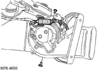
4. Disconnect the block from the heater fan electric motor.
5. Turn out 2 screws of fastening of the electric motor of a heater to an arm.
6. Release and remove the heater electric motor.
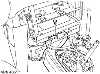
7. Remove the retainer securing the center console heater air duct to the heater-fan-air conditioner unit (HEVAC) and remove the heater duct.
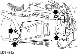
8. Remove the 4 screws securing the center console heater motor bracket to the floor transmission tunnel.
9. Remove an arm of the electric motor of a heater of the central console.
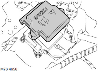
10. Loosen and remove the cover from the diagnostic unit (DCU).
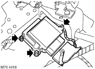
11. Disconnect the connector block from the diagnostic unit.
12. Turn away a fastening nut "mass" wires to the diagnostic unit. Remove "mass" the wire.
13. Turn out 2 screws of fastening of the diagnostic block to the transmission tunnel. Remove the diagnostic block.
WARNING: The SRS diagnostic unit is shock sensitive and should be handled with care.
Assembly
1. Install the diagnostic unit on the transmission tunnel, connect "mass" wire, screw on the nuts and tighten them with a torque of 10 Nm.
NOTE: If a SRS component needs to be replaced, note down the barcode of the new component.
2. Connect the block to the connector of the diagnostic unit.
3. Install and fix the cover on the diagnostic unit.
4. Install the heater motor bracket on the transmission tunnel, tighten the screws and tighten them with a torque of 25 Nm.
5. Install the center console heater air duct on the HEVAC unit and secure it with the clips.
6. Install the heater motor on the bracket and fix it with screws.
7. Connect the shoe to the heater motor.
8. Reinstall the air suspension control panel.
CAR INTERIOR PARTS, REPAIR WORKS, Switch panel - air suspension.
9. Reinstall the center console.
CAR INTERIOR PARTS, REPAIR WORKS, Center console.
10. Connect the battery terminals, first "positive" terminal.
11. Initialize the system using the TestBook/T4 diagnostic tool.
Comments on this article