Contents: Location of antennas and amplifiers ⇩ Antenna placement in glass ⇩ FM Antenna Booster ⇩ TMC Antenna Booster ⇩ GPS satellite antenna ⇩ TV Antenna Amplifier ⇩ Multi-band telephone antenna ⇩ SDARS Satellite Digital Radio…⇩ VICS Transponder Antenna (for Japan…⇩
Location of antennas and amplifiers
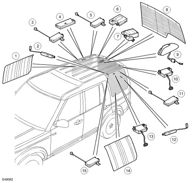
| Item name | Spare part catalog number | Description |
| 1 | FM Antenna | |
| 2 | Suppressor | |
| 3 | TV Antenna Amplifier | |
| 4 | FM Antenna Booster Tuning to the Best Station | |
| 5 | TV Antenna Amplifier | |
| 6 | - | FM Antenna Booster |
| 7 | - | GPS Antenna |
| 8 | - | Antennas in the glass of the luggage compartment door |
| 9 | - | Telephone Antennas and SDARS Systems |
| 10 | - | Antenna amplifier VICS/TMC |
| 11 | - | TV Antenna Amplifier |
| 12 | - | Suppressor |
| 13 | - | VICS Antenna Booster |
| 14 | - | TV antennas in the side glass |
| 15 | - | TV Antenna Amplifier |
Antenna placement in glass
NOTE: A = Wired connection
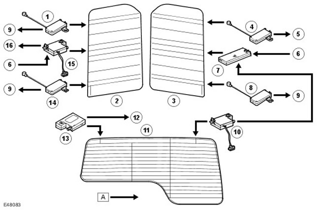
| Item name | Spare part catalog number | Description |
| 1 | TV Antenna Amplifier | |
| 2 | Antennas in the left side glass | |
| 3 | Antennas in the right side glass | |
| 4 | - | TV Antenna Amplifier |
| 5 | - | TV tuner module |
| 6 | - | Integrated Head Unit (IHU) |
| 7 | - | AM/FM Antenna Booster Tuning to the Best Station |
| 8 | - | TV Antenna Amplifier |
| 9 | - | TV receiver module |
| 10 | - | FM receiver amplifier tuning to the best station |
| 11 | - | Antennas in the glass of the luggage compartment door |
| 12 | - | VICS/TMC Tuner |
| 13 | - | Antenna amplifier VICS/TMC |
| 14 | - | TV Antenna Amplifier |
| 15 | - | VICS Antenna Booster |
| 16 | - | VICS Tuner |
Car antenna systems include the following elements:
- aM antenna (embedded in glass)
- fM antenna (embedded in glass)
- fM antenna tuning to the best station (if present, mounted in glass)
- tV antenna (if present, mounted in glass)
- multi-band telephone antenna (if available, installed on the roof)
- gPS antenna (if available, installed on the rear spoiler)
- sDARS antenna (uS only, roof mounted)
- vICS antenna and infrared antenna (if available, only for Japan)
FM Antenna Booster
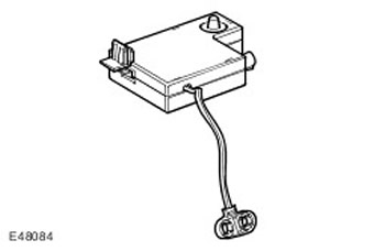
The AM/FM antennas are mounted in the side glass and the rear window. In vehicles with the standard audio system, the AM/FM antenna is mounted in the right rear window. Vehicles with the premium audio system are equipped with an FM station preset. This allows the system to automatically select the stronger of the two signals received to provide the best possible reception of the FM station. The basic AM/FM antenna, mounted in the right rear window, is connected to an antenna amplifier located above the window. In addition to the amplifier and the antenna in the side window, the station preset also uses the heated rear window antenna and the FM antenna amplifier mounted at the top of the rear window.
TMC Antenna Booster
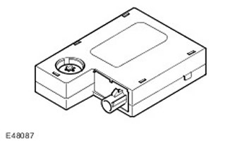
Traffic Message Channel (TMC) signals are received as normal radio signals via the Radio Data System (RDS) network. However, these signals are transmitted on separate circuits via a dedicated antenna amplifier located on the right rear window. For more information, refer to Navigation System (419-07 Navigation System)
GPS satellite antenna
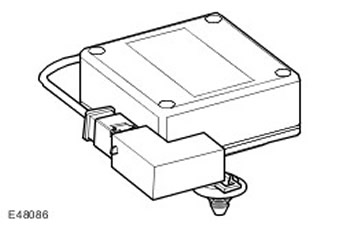
The GPS antenna is located in the upper spoiler of the luggage compartment, on its right side. The GPS antenna is connected to the navigation system computer via a coaxial cable. For more information, refer to Navigation System (419-07 Navigation System)
TV Antenna Amplifier
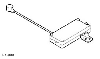
If the vehicle is equipped with a TV system, it uses 4 antennas, two in each rear side window. Each antenna uses a separate antenna amplifier connected to the TV module using a coaxial cable. For more information, refer to Video System (415-07 Video System)
Multi-band telephone antenna
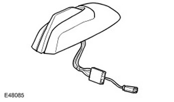
The multi-band telephone antenna is built into a housing mounted on the center rear roof of the vehicle and is connected directly to the Telephone Control Module (TCM) via a coaxial cable. For more information, refer to Cellular Phone (419-08 Cellular Phone)
SDARS Satellite Digital Radio Antenna (for USA only)
The material was taken from the specified website: www.lrman.ru
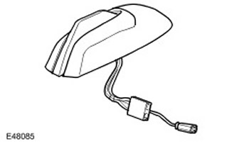
The SDARS antenna is built into a housing mounted on the central rear part of the vehicle roof. The antenna has two connectors for connection to the receiver: the first is for satellite communication, and the second is for ground communication with relay stations.
The antenna consists of two main components:
- printed dipole antenna for receiving signals from satellites
- printed single-pole antenna for receiving signals from ground stations
VICS Transponder Antenna (for Japan only)
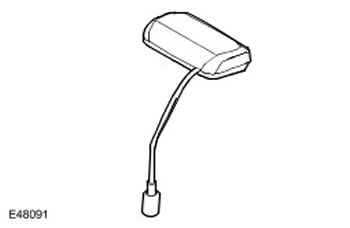
To receive data, the VICS controller uses an antenna located in the rear right window. In addition, the VICS controller uses an infrared antenna mounted on the center top of the instrument panel near the sun sensor. For more information, refer to Navigation System (419-07 Navigation System)
Comments on this article