Contents: Low Level Audio System Layout ⇩ Audio system head unit control…⇩ Layout of integrated head unit (IHU)…⇩ Integrated Head Unit (IHU) Audio…⇩ Head units of audio systems ⇩ Head unit of standard audio system ⇩ Standard audio system control unit…⇩ Radio receiver functions ⇩ CD Player Functions (compact disc) ⇩ Integrated audio head unit ⇩ Contacts of connector C1354 of the…⇩ C2115 connector pinout table ⇩ Radio ⇩ CD player (compact disc) ⇩ Automatic Volume Control (AVC) ⇩ Watch ⇩ High-quality amplifier Harman Kardon…⇩ C0491 Speaker Connector for Harman…⇩ C0491 Speaker Connector for Harman…⇩ C0492 Speaker Connector for Harman…⇩ C0493 Speaker Connector for Harman…⇩ C0492 Speaker Connector for Harman…⇩ C0493 Speaker Connector for Harman…⇩ Steering wheel mounted audio controls ⇩ Satellite digital radio (sDARS…⇩ Traffic Management Message Channel…⇩
Low Level Audio System Layout
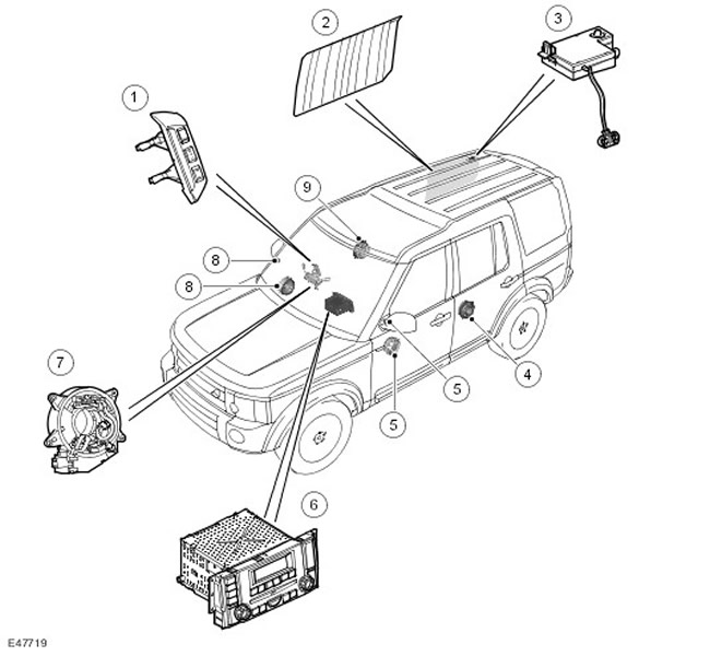
| Item name | Spare part catalog number | Description |
| 1 | - | Audio control switches |
| 2 | - | Antennas in glass |
| 3 | - | Antenna amplifier |
| 4 | - | Rear LH (left) door speakers |
| 5 | - | Front LH (left) door speakers |
| 6 | - | Head unit of the audio system |
| 7 | - | Movable contact group |
| 8 | - | Front RH (right) door speakers |
| 9 | - | Rear RH (right) door speakers |
Audio system head unit control diagram
NOTE: A = Wired
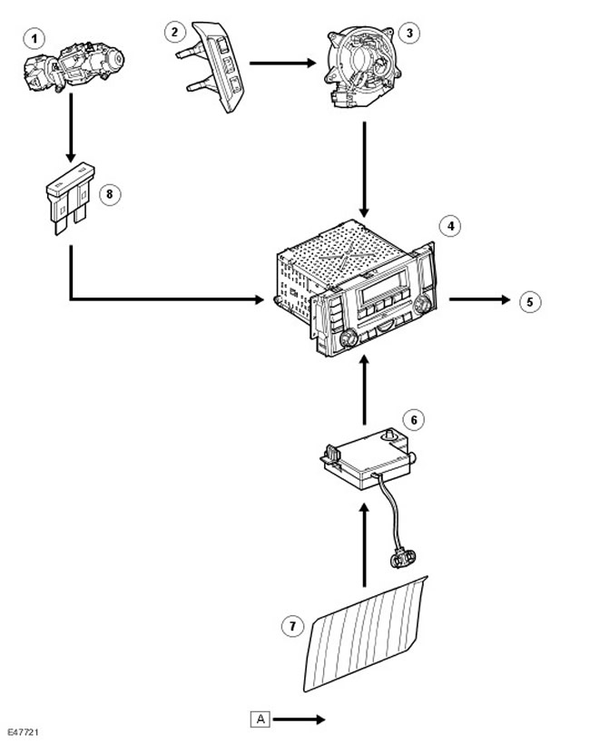
| Item name | Spare part catalog number | Description |
| 1 | - | Ignition switch |
| 2 | - | Remote control for audio system |
| 3 | - | Movable contact group |
| 4 | - | Head unit of the audio system |
| 5 | - | Speakers |
| 6 | - | Antenna amplifier |
| 7 | - | AM Antenna (amplitude modulation)/FM (frequency modulation) |
| 8 | - | Fuse |
Layout of integrated head unit (IHU) audio system components
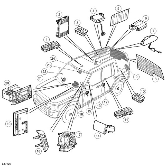
| Item name | Spare part catalog number | Description |
| 1 | - | Remote control for audio system (second row of seats) |
| 2 | - | TMC Tuner |
| 3 | - | Remote control for audio system (third row of seats) |
| 4 | - | Antenna amplifier |
| 5 | - | AM Antenna (amplitude modulation)/FM (frequency modulation) in the side glass |
| 6 | - | Antenna amplifier tuning to the best station |
| 7 | - | SDARS / Roof Mounted Telephone Antenna Adapter |
| 8 | - | Antennas in the glass of the luggage compartment door |
| 9 | - | Subwoofer |
| 10 | - | Remote control for audio system (third row of seats) |
| 11 | - | Remote control for audio system (second row of seats) |
| 12 | - | Midrange speaker |
| 13 | - | High frequency speaker (tweeter) |
| 14 | - | Audio-video signal input/output panel |
| 15 | - | Midrange speaker |
| 16 | - | High frequency speaker (tweeter) |
| 17 | - | Movable contact group |
| 18 | - | Remote control for audio system |
| 19 | - | Audio amplifier |
| 20 | - | Integrated Head Unit (IHU) |
| 21 | - | Midrange speaker |
| 22 | - | High frequency speaker (tweeter) |
| 23 | - | Midrange speaker |
| 24 | - | High frequency speaker (tweeter) |
Integrated Head Unit (IHU) Audio Control Schematic
NOTE: A = Wired connection; P = MOST bus
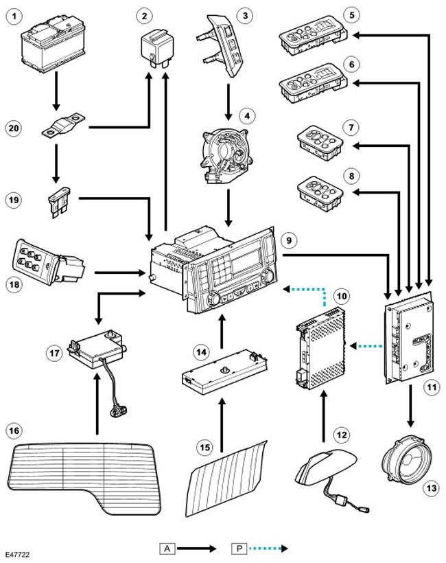
| Item name | Spare part catalog number | Description |
| 1 | - | Battery |
| 2 | - | Infotainment System Main Relay |
| 3 | - | Remote control for audio system |
| 4 | - | Movable contact group |
| 5 | - | Remote control for audio system (second row of seats) |
| 6 | - | Remote control for audio system (second row of seats) |
| 7 | - | Remote control for audio system (third row of seats) |
| 8 | - | Remote control for audio system (third row of seats) |
| 9 | - | Integrated Head Unit (IHU) |
| 10 | - | Tuner SDARS |
| 11 | - | Audio amplifier |
| 12 | - | SDARS / Roof Mounted Telephone Antenna Adapter |
| 13 | - | Speakers |
| 14 | - | Antenna amplifier in the side window for tuning to the best station |
| 15 | - | AM Antenna (amplitude modulation)/FM (frequency modulation) in the side glass |
| 16 | - | Antennas in the glass of the luggage compartment door |
| 17 | - | Antenna amplifier in the glass of the luggage compartment door |
| 18 | - | Audio-video signal input/output panel |
| 19 | - | Fuse 53p |
| 20 | - | Fuse link 18E |
Head units of audio systems
Cars can be equipped with a standard audio system or a premium audio system. The architecture of the standard audio system is built around the head unit, which communicates with other units via the CAN bus. (local area network of controllers) medium data rate, and the high-end audio system architecture is centered around an integrated head unit (IHU) that communicates with other nodes over the media system data network (Media Orientated System Transport - MOST) and CAN bus (local area network of controllers) average data transfer rate.
Head unit of standard audio system
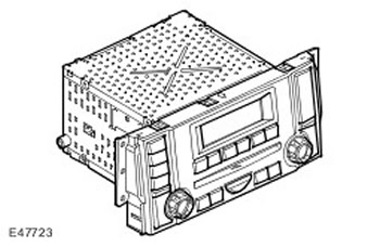
The head unit of a standard audio system has the following components:
- Radio
- CD player (compact disc) on one disk
- Amplifier
Standard audio system control unit connector C1354 contacts
| Contact No. | Description | Input signal/output signal |
| 1 | "Mass" of the power circuit | - |
| 2 | ||
| 3 | (+) rear LH (left) speaker | Output signal |
| 4 | (-) rear LH (left) speaker | - |
| 5 | (+) rear RH (right) speaker | Output signal |
| 6 | (-) rear RH (right) speaker | - |
| 7 | Steering wheel audio control switches signal | Input signal |
| 8 | Not used | - |
| 9 | (+) CAN bus input (local area network of controllers) | Input signal |
| 10 | (-) CAN bus output (local area network of controllers) | - |
| 11 | Battery voltage | Input signal |
| 12 | (+) antenna power | Output signal |
| 13 | (-) front LH (left) speaker | - |
| 14 | (+) front LH (left) speaker | Output signal |
| 15 | (-) front RH (right) speaker | - |
| 16 | (+) front RH (right) speaker | Output signal |
| 17 | Not used | - |
| 18 | (+) Reference voltage for steering wheel audio controls | Output signal |
| 19 | (+) CAN bus output (local area network of controllers) | Output signal |
| 20 | (-) CAN bus output (local area network of controllers) | - |
The head unit has a power management function. If the battery voltage drops below a specified level, the unit limits the execution of some functions. The head unit receives CAN signals (local area network of controllers), which allow you to determine the need for switching on/off. The following are the switching on/off conditions associated with the ignition switch control.
- If CAN bus activity is detected (local area network of controllers) and the battery voltage exceeds 12.3 V, on the LCD (liquid crystal display) the head unit displays the clock.
- If the head unit is turned on with the ignition key in the ignition switch and the ignition switch is turned to the ACC/AUX position, the audio head unit operates normally in power saving mode for 1 hour.
- If the key is turned from the ACC/AUX position to the IGN/RUN position, all head unit functions are still performed.
- When the key is turned from IGN/RUN to the engine start position, the sound is turned off while the engine is cranking.
- If engine cranking is completed and the ignition key is returned to the IGN/RUN position, the head unit operates in the normal power mode.
- When the key is turned from the IGN/RUN position to the ACC/AUX position, the head unit enters power saving mode, limiting the output volume.
- If the key is turned from the ACC/AUX position to the off position, the head unit operates in power saving mode for 10 minutes. After the specified time has elapsed, the head unit goes into standby mode. If the key is not removed and the CAN network (local area network of controllers) goes into standby mode, the head unit switches off. The head unit will only switch on again if one of the following conditions is met: the door locks change from locked to unlocked, the ignition key is turned from off to the ACC/AUX position, the head unit power button is pressed, CD (compact disc) is inserted or removed.
- When the key is removed, the head unit goes into standby mode. The only exception is when the key is removed during a telephone conversation. Until the end of the conversation, the head unit remains on, and after the end, it goes into standby mode.
Transport mode
The transport mode is used to reduce the battery discharge during storage or transportation of the vehicle. The transport mode is started/deactivated by T4 via CAN signals. (local area network of controllers). In transport mode, the following circuits are switched off:
- Amplifiers
- External signal source and telephone
- Watch
- Antenna power supply
- LED Power Supply (Light Emitting Diode)
CAN connector (local area network of controllers) remains open to receive the EXIT signal from the transport mode. The power switch remains on to display a message on the LCD () of the head unit that the unit is in transport mode when you try to turn on the head unit. The message is displayed only if the vehicle is moving and the battery voltage is above 12.3 V.
Radio receiver functions
The radio receiver is located in the head unit. The radio receiver is capable of receiving AM and FM radio signals and storing 18 FM stations and 12 AM stations. (amplitude modulation). AM stations (amplitude modulation) are remembered as follows:
Saving stations of the range in models for European countries
- 6 MW
- 6 MWa
- 6 LW
- 6 LWa
- 6 MW1
- 6 MW2
- 6 MWa
CD Player Functions (compact disc)
The head unit contains a CD player with the ability to play one CD (compact disc). This CD player (compact disc) has all the functions typical of all CD players (compact disc):
- Play CD (compact disc)
- Previous / Next Entry
- Playback of recordings in random order
- Loading/Ejecting CD (compact disc)
- Scanning a CD
- Repeat playback
Integrated audio head unit
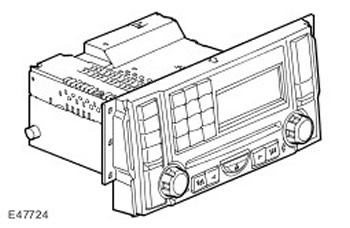
The head unit of the high-end audio system has the following components:
- Radio.
- CD player (compact disc) (with built-in six-CD changer).
- Built-in telephone communication controller.
- Additional input jack (for any device with a 3.5mm plug).
The IHU unit is switched on via a signal on the CAN bus. (local area network of controllers), and not when the ignition switch is turned to the AUX position.
The IHU is the master subscriber of the MOST bus and contains the MOST system synchronizer.
Contacts of connector C1354 of the control unit of the audio system of the premium class system
| Contact No. | Description | Input signal/output signal |
| 1 | "Weight" | - |
| 2 | Not used | - |
| 3 | Not used | - |
| 4 | Not used | - |
| 5 | Not used | - |
| 6 | Not used | - |
| 7 | "Mass" of switches on the steering wheel | - |
| 8 | Infotainment system relay | Output signal |
| 9 | (+) CAN bus (local area network of controllers) | Input signal |
| 10 | (-) CAN bus (local area network of controllers) | Output signal |
| 11 | Battery voltage | Input signal |
| 12 | Antenna power supply | Output signal |
| 13 | Not used | - |
| 14 | Not used | - |
| 15 | Not used | - |
| 16 | Not used | - |
| 17 | Not used | - |
| 18 | Steering wheel switch reference voltage | Output signal |
| (+) CAN bus (local area network of controllers) | Input signal | |
| (-) CAN bus (local area network of controllers) | Output signal |
C2115 connector pinout table
| Contact No. | Description | Input signal/output signal |
| 1 | Not used | - |
| 2 | Not used | - |
| 3 | (+) phone | Output signal |
| 4 | Not used | - |
| 5 | (-) phone | - |
| 6 | Additional screen | - |
| 7 | Right-hand socket for connecting additional equipment | Input signal |
| 8 | Left plug socket for connecting additional equipment | Input signal |
| 9 | Not used | - |
| 10 | Not used | - |
| 11 | Not used | - |
| 12 | Lots of sound signals | - |
Radio
The IHU contains the AM receiver. (amplitude modulation)/FM (frequency modulation), which can store 18 stations in the FM range in its memory (frequency modulation) and 12 - in the AM range (amplitude modulation) (6 in the medium wave range and 6 in the long wave range). The radio receiver also has the following functions:
- Automatic tuning to the station
- Reception of traffic information (TA)
- EON function of RDS system (radio data transmission system)
- Search stations
- Tuning in forward and reverse directions
CD player (compact disc)
The CD player is a built-in device designed for 6 CDs (compact disc). CD player (compact disc) can play commercial CDs (compact disc), compact discs of CD formats (compact disc) R and CD (compact disc) RW and compact discs with MP3 recordings.
Play recordings in random order
The random play function only works on selected CDs. (compact disc). When the random play function is enabled, all tracks on the selected CDs are played in random order. (compact disc) are played in random order. A new playback sequence is created only after all tracks on the disc have been played. If a new CD is selected for playback (compact disc) in random play mode, random play mode is canceled and playback starts from track 1.
Repeat playback
The user can select the cyclic repeat playback mode of the current audio track.
MP3
CD player (compact disc) supports playback of MP3 files. This format allows you to group files into folders. You can also place all files in the root directory on the CD (compact disc).
The random and repeat play functions work the same as for regular CDs. (compact disc).
Scanning a CD
The CD Scan function allows you to play the first 10 seconds of each track on the CD (compact disc), inserted into the block.
Automatic Volume Control (AVC)
Automatic volume control helps compensate for the increase in noise levels generated by the vehicle as the speed increases.
There are 10 levels of AVC system settings: 0 - the system is off, 1 - minimum increase in volume with increasing speed, and then up to 9 - maximum increase in volume.
To calculate the required volume change, the IHU uses signals from the speed sensors. The vehicle speed signal comes via the CAN bus. (local area network of controllers) from ABS control module (anti-lock braking system). The average value of the speeds of the four wheels is used.
The AVC system is controlled directly by the audio system amplifier.
If the AVC system receives an erroneous vehicle speed signal, the system does not change the current volume value.
Watch
The IHU unit functions as the main system clock. The clock and dial are combined into one unit located in the IHU. Other vehicle modules that require the time function receive their data from the IHU unit.
Any module connected to the interconnection bus, i.e. to any CAN bus (local area network of controllers) or the MOST system.
The display can show the time in 12-hour format (a.m. and p.m.), and can also be set to 24-hour format. Accordingly, midnight is indicated as 12:00 AM or 0:00. When power is connected, the default clock (if there are no other settings) will show 1:00PM or 1:00PM. Depending on the market, the clock defaults to either the 12-hour or 24-hour format.
The time is set via the IHU. This ensures that the time is always synchronized across all vehicle devices. If any of the data buses are currently disconnected or in "sleep" mode, the system does not allow the clock to be adjusted.
High-quality amplifier Harman Kardon Logic 7
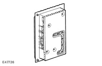
Cars are equipped with one of the following two amplifiers:
- Harman Kardon
- Harman Kardon Logic 7
C0491 Speaker Connector for Harman Kardon Amplifier
| Contact No. | Description | Input signal/output signal |
| 1 | (-) rear LH (left) door dynamics | - |
| 2 | (-) rear RH (right) door speaker | - |
| 3 | Not used | - |
| 4 | Not used | - |
| 5 | (-) front LH (left) door dynamics | - |
| 6 | (-) front RH (right) door dynamics | - |
| 7 | (-) left subwoofer | - |
| 8 | (-) right subwoofer | - |
| 9 | (+) dynamics of the rear LH (left) door | Output signal |
| 10 | (+) dynamics of the rear RH (right) door | Output signal |
| 11 | Not used | - |
| 12 | Not used | - |
| 13 | (+) front LH (left) door dynamics | Output signal |
| 14 | (+) front RH (right) door dynamics | Output signal |
| 15 | (+) left subwoofer | Output signal |
| 16 | (+) right subwoofer | Output signal |
C0491 Speaker Connector for Harman Kardon Logic 7 Amplifier
| Contact No. | Description | Input signal/output signal |
| 1 | (-) rear LH (left) door dynamics | - |
| 2 | (-) rear RH (right) door speaker | - |
| 3 | (-) front LH (left) low frequency speaker | - |
| 4 | (-) front RH (right) low frequency speaker | - |
| 5 | (-) rear left surround speaker | - |
| 6 | (-) rear right surround speaker | - |
| 7 | (-) left subwoofer | - |
| 8 | (-) right subwoofer | - |
| 9 | (+) dynamics of the rear LH (left) door | Output signal |
| 10 | (+) dynamics of the rear RH (right) door | Output signal |
| 11 | (+) front LH (left) low frequency speaker | Output signal |
| 12 | (+) front RH (right) low frequency speaker | Output signal |
| 13 | (+) Rear Left Surround Speaker | Output signal |
| 14 | (+) Rear Right Surround Speaker | Output signal |
| 15 | (+) left subwoofer | Output signal |
| 16 | (+) right subwoofer | Output signal |
C0492 Speaker Connector for Harman Kardon Amplifier
| Contact No. | Description | Input signal/output signal |
| 1 | Not used | |
| 2 | Not used | |
| 3 | Not used | |
| 4 | Not used | |
| 5 | Left channel of the 1st headphone module | Output signal |
| 6 | "Mass" of the right channel of the 1st module of headphones | Output signal |
| 7 | "Mass" of the right channel of the 2nd module of headphones | Output signal |
| 8 | Left channel of the 2nd headphone module | Output signal |
| 9 | Not used | - |
| 10 | Not used | - |
| 11 | Not used | - |
| 12 | Not used | - |
| 13 | Not used | - |
| 14 | Not used | - |
| 15 | "Mass" of the left channel of the 1st module of headphones | - |
| 16 | "Mass" of the right channel of the 1st module of headphones | - |
| 17 | "Mass" of the left channel of the 2nd module of headphones | - |
| 18 | "Mass" of the right channel of the 2nd module of headphones | - |
| 19 | Not used | - |
| 20 | Not used | - |
C0493 Speaker Connector for Harman Kardon Amplifier
| Contact No. | Description | Input signal/output signal |
| 1 | Left channel of the 3rd headphone module | Output signal |
| 2 | "Mass" of the right channel of the 3rd module of headphones | Output signal |
| 3 | Left channel of the 4th headphone module | Output signal |
| 4 | "Mass" of the right channel of the 4th module of headphones | Output signal |
| 5 | Control signal of the 1st headphone module | Output signal |
| 6 | Control signal of the 2nd headphone module | Output signal |
| 7 | Control signal of the 3rd headphone module | Output signal |
| 8 | Control signal of the 4th headphone module | Output signal |
| 9 | Not used | |
| 10 | Not used | |
| 11 | "Mass" of the left channel of the 3rd module of headphones | - |
| 12 | "Mass" of the right channel of the 3rd module of headphones | - |
| 13 | "Mass" of the left channel of the 4th module of headphones | - |
| 14 | "Mass" of the right channel of the 4th module of headphones | - |
| 15 | "Mass" of the control signal of the 1st module of headphones | - |
| 16 | "Mass" of the control signal of the 2nd headphone module | - |
| 17 | "Mass" of the control signal of the 3rd module of headphones | - |
| 18 | "Mass" of the control signal of the 4th module of headphones | - |
| 19 | Not used | - |
| 20 | Not used | - |
C0492 Speaker Connector for Harman Kardon Logic 7 Amplifier
| Contact No. | Description | Input signal/output signal |
| 1 | (-) Front LH (left) midrange/tweeter | - |
| 2 | (-) Front RH (Right) Mid/Tweeter | - |
| 3 | (-) middle "filling" speaker | - |
| 4 | Not used | - |
| 5 | Left channel of the 1st headphone module | Output signal |
| 6 | "Mass" of the right channel of the 1st module of headphones | Output signal |
| 7 | Left channel of the 2nd headphone module | Output signal |
| 8 | "Mass" of the right channel of the 2nd module of headphones | Output signal |
| 9 | Not used | - |
| 10 | Not used | - |
| 11 | (+) front LH (left) midrange/high frequency speaker | Output signal |
| 12 | (+) Front RH (right) midrange/high frequency speaker | Output signal |
| 13 | (+) middle "filling" speaker | Output signal |
| 14 | Not used | - |
| 15 | "Mass" of the left channel of the 1st module of headphones | - |
| 16 | "Mass" of the right channel of the 1st module of headphones | - |
| 17 | "Mass" of the left channel of the 2nd module of headphones | - |
| 18 | "Mass" of the right channel of the 2nd module of headphones | - |
| 19 | Not used | - |
| 20 | Not used | - |
C0493 Speaker Connector for Harman Kardon Logic 7 Amplifier
| Contact No. | Description | Input signal/output signal |
| 1 | Left channel of the 3rd headphone module | Output signal |
| 2 | "Mass" of the right channel of the 3rd module of headphones | Output signal |
| 3 | Left channel of the 4th headphone module | Output signal |
| 4 | "Mass" of the right channel of the 4th module of headphones | Output signal |
| 5 | Control signal of the 1st headphone module | Output signal |
| 6 | Control signal of the 2nd headphone module | Output signal |
| 7 | Control signal of the 3rd headphone module | Output signal |
| 8 | Control signal of the 4th headphone module | Output signal |
| 9 | Not used | - |
| 10 | Not used | - |
| 11 | "Mass" of the left channel of the 3rd module of headphones | - |
| 12 | "Mass" of the right channel of the 3rd module of headphones | - |
| 13 | "Mass" of the left channel of the 4th module of headphones | - |
| 14 | "Mass" of the right channel of the 4th module of headphones | - |
| 15 | "Mass" of the control signal of the 1st module of headphones | - |
| 16 | "Mass" of the control signal of the 2nd headphone module | - |
| 17 | "Mass" of the control signal of the 3rd module of headphones | - |
| 18 | "Mass" of the control signal of the 4th module of headphones | - |
| 19 | Not used | - |
| 20 | Not used | - |
Steering wheel mounted audio controls
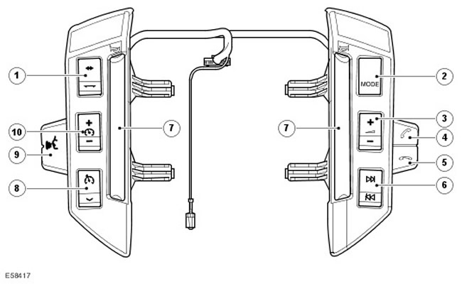
| Item name | Spare part catalog number | Description |
| 1 | Adaptive Cruise Control Distance Control Switches | |
| 2 | Audio mode selector switch | |
| 3 | Volume control | |
| 4 | Start talk key | |
| 5 | End call key | |
| 6 | Audio system search switch | |
| 7 | Sound signal | |
| 8 | Cruise control and cruise control switch | |
| 9 | Voice recognition system switch | |
| 10 | Cruise control speed control switch |
The steering wheel mounted switches allow remote control of the IHU. The audio controls are located on the right side of the steering wheel.
The controls are resistive multi-link switches. The IHU supplies a reference voltage to the switches, which transmit a modified voltage to the IHU depending on which switch is pressed.
Using the controls you can adjust the volume, switch tracks on the CD (compact disc) or radio stations, start or end a conversation (if the car is equipped with a telephone), and also control the voice recognition system.
Satellite digital radio (sDARS system - US only)
SDARS systems operate in the ultra-high frequency range (2.3 GHz) and, thanks to the use of satellite data transmission, provide broadcasting with high sound quality (comparable to the quality of CD recordings (compact disc)) over a very large area (usually continents). Network providers transmit various information from their enterprises to the satellite: data, speech, etc. via an antenna system. The satellite transmits this information both to ground relay stations and to autonomous SDARS receivers, including automobile ones. The receiver is capable of switching at any time from receiving a signal from the satellite to receiving the strongest signal coming from the relay station.
Land Rover uses the services of the American provider Sirius Satellite Radio.
The SDARS Sirius system includes:
- Earth satellites
- Ground repeaters
- Ground transmitting stations
- Radio reception systems
Signals from satellites are captured by receivers or sent to repeaters, which allows transmissions to be received even if the satellite is not within direct line of sight.
Traffic Management Message Channel (TMC)
The TMC system operates only in Europe. Traffic information is received by the TMC receiver and used by the navigation system computer to calculate a route, avoiding traffic jams and other obstacles. This information is transmitted to RDS data carriers (radio data transmission system).
Comments on this article