The headlights are located behind the front carrier panel assembly. Each headlamp is attached to the front carrier panel with two locking bars. The locking strips move in the grooves on the back of the headlights and are fixed with their holes on the pins of the front carrier panel. To secure, each locking bar is pressed down so that the pins fit into the holes. Locking strips make it possible to remove the headlamp from the carrier panel to replace the lamps without the use of special tools.
On the rear wall of the headlight there is a removable panel that provides access to the lamps for their replacement. The large cover, which is removed by turning it counterclockwise, gives access to both halogen and xenon low and high beam lamps. Another cover allows access only to the high beam halogen lamp, which is held by a spring latch. The small cover can also be removed by turning counterclockwise to expose the turn signal bulb. Beneath this cover is a removable cover that provides access to the position light bulb, cornering light/pivot side light bulb and side marker light bulb (US models).
At the rear of the headlight unit there are two screws for manual adjustment of the headlight axis in the vertical and horizontal planes. On vehicles for the US market (NAS) headlights have the direction of the optical axes 'Visual Optically Left' (VOL). The adjustment screws must be turned by the same number of turns in order to ensure that the headlight adjustment ratios are only vertical. Adjustment in the horizontal plane is not provided. The headlight adjustment procedure is outlined in the Repair Manual.
Each headlight is equipped with a 16-pin connector that provides the input and output signals for the functional support of the headlight. Connector pin assignments may vary from model to model, see the Electrical Reference Library for details (ERL).
The dipped beam headlights come on when the ignition switch is in the (II) And:
- The light switch is in the headlights on position
- The light switch is in the AUTO position and the central switching unit receives a signal from the rain / light sensor to turn on the outdoor lighting.
The high beam headlights turn on when the ignition switch is in the (II) And:
- the dipped beam headlights are switched on either by the light switch or by using the AUTO function
- The left multifunction stalk is moved forward, away from the driver.
- Left multifunction stalk shifted back towards the driver
- Low beam headlights off
- Ignition switch is turned from position I (auxiliary equipment power supply) to position 0 (turned off).
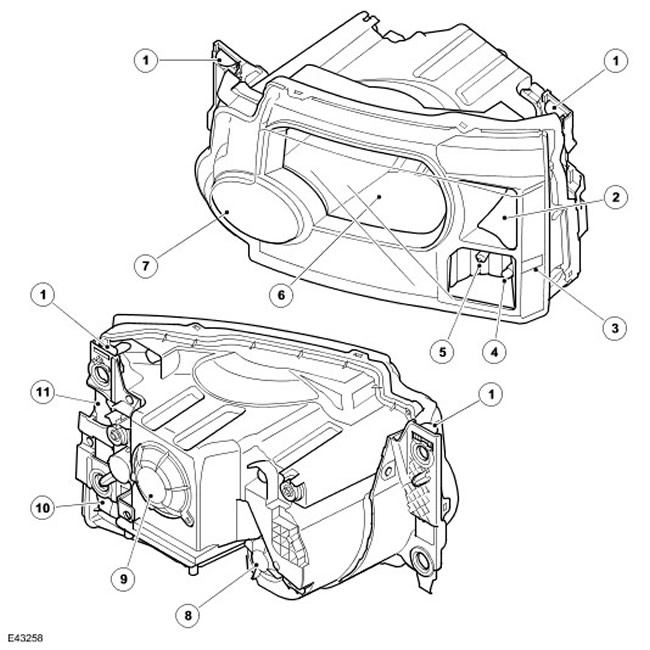
Halogen headlights
| Item name | Spare part number | Description |
| 1 | - | lock bar |
| 2 | - | Turn indicator |
| 3 | - | Side marker lamp (US only) |
| 4 | - | Marker lamp |
| 5 | - | Side lighting for cornering (if available) |
| 6 | - | Low / high beam headlight |
| 7 | - | high beam headlight |
| 8 | - | Service hatch cover for high beam |
| 9 | - | Service hatch cover for dipped/main beam headlights |
| 10 | - | Cover of the service hatch of a dimensional lamp (not shown) |
| 11 | - | Turn signal service hatch cover (not shown) |
Halogen headlights use a complex shaped reflector for the dipped and high beam headlamps. The reflector is divided into two parabolic segments with different focal lengths. When driving in countries with opposite traffic, a special light-protective sticker must be glued to the outer surface of the halogen headlight lens to block part of the light beam.
The dipped and main beam headlights use halogen lamps with a quartz bulb with a power of 55 watts. The bulbs are attached to the headlamp housing with conventional wire clamps.
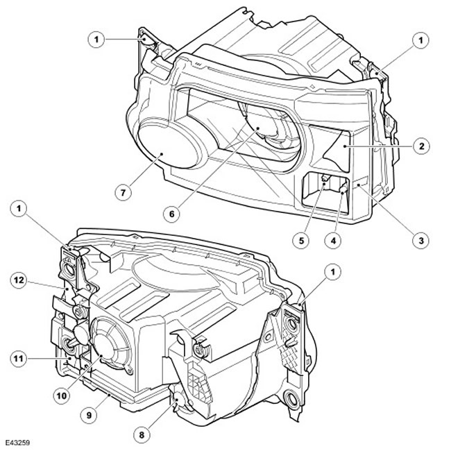
Xenon headlights
| Item name | Spare part number | Description |
| 1 | - | lock bar |
| 2 | - | Turn indicator |
| 3 | - | Side marker lamp (US only) |
| 4 | - | Marker lights |
| 5 | - | Side lighting for cornering (if available) |
| 6 | - | Xenon dipped/high beam |
| 7 | - | Halogen high beam |
| 8 | - | Service hatch cover for high beam |
| 9 | - | xenon headlight controller |
| 10 | - | Service hatch cover for dipped/main beam headlights |
| 11 | - | Cover of the service hatch of a dimensional lamp (not shown) |
| 12 | - | Turn signal service hatch cover (not shown) |
Precautionary measures
WARNING: Xenon lamp supply voltage reaches 28000 V. Contact with such voltage can be fatal. Before carrying out work on the headlights, they must be turned off.
When working with a xenon lighting system, the following precautions must be observed:
- It is FORBIDDEN to carry out any work on the xenon lighting system with the external lighting switched on.
- Work with D2S xenon lamps is possible only with the use of personal protective equipment, such as gloves and goggles. Do not touch the glass bulb of the lamp.
- Disposal of xenon lamps must be carried out according to the rules for the disposal of hazardous waste.
- You can turn on the lamp only when it is in the working position, that is, in its cartridge.
The high beam headlight uses a halogen lamp with a 55W quartz bulb. The bulbs are attached to the headlamp housing with conventional wire clamps.
The xenon unit headlight is called dual-mode xenon headlight and works as a low beam headlight and a high beam headlight. As part of a xenon or gas-discharge (HID) headlights includes a curtain controlled by an electromagnet, changing the beam of the high beam to the beam of the dipped beam and vice versa.
NOTE: If the light switch is in the off position, the xenon high beam signaling is not possible. If the light switch is in the headlights on position or in the AUTO position and the dipped beam headlights are on, the xenon dipped beam remains on when signaling the high beam of the xenon headlights.
The operation of the xenon headlights is controlled by the CJB unit, which is connected to the controllers of each of the headlights and to the discharge starter. The xenon headlight controller and starter provide the xenon lamp with enough electricity to turn it on.
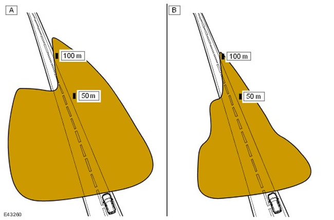
Comparison of illumination patterns of xenon and halogen headlights
| Item name | Spare part number | Description |
| A | - | Xenon Dual Mode Headlight |
| B | - | Halogen |
Xenon headlights use reflectors and lenses made using the so-called ellipsoidal technology and provide better illumination in comparison with halogen headlights in the dark. Compared to halogen headlights, xenon headlights offer the following advantages:
- Long service life of xenon lamps - approximately 3-5 times longer than halogen lamps
- Increased light output: the luminous flux of xenon headlights is 3-4 times higher than that of halogen headlights
- Blue/white light closer to natural daylight - xenon lamps produce blue/white light compared to the yellow light produced by halogen lamps
- Better visibility when driving at night - xenon lamps produce a wider and brighter beam of light than conventional halogen lamps
- Lower heat dissipation
- Less electricity consumption
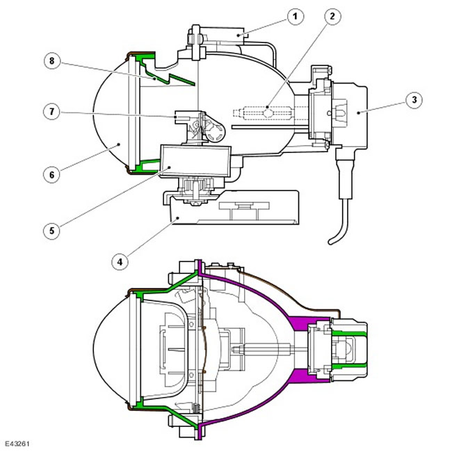
Design of xenon headlights
| Item name | Spare part number | Description |
| 1 | - | bracket |
| 2 | - | Xenon lamp DS2 |
| 3 | - | DS2 connector |
| 4 | - | Motor reducer of course drive of headlights (only for adaptive headlights) |
| 5 | - | Electromagnet |
| 6 | - | Aspherical diffuser |
| 7 | - | shader |
| 8 | - | shader |
| 9 | - | diffuser support |
The xenon headlight is an independent structural element, which is located in the headlight unit. This unit consists of a reflector, an adapter ring, a diffuser, a screen controller and a xenon lamp, and the assembly is called a spotlight.
The diffuser has a convex shape and secures a xenon lamp in it. The lamp sits in a groove to ensure proper alignment in the reflector and is secured by pushing and turning to the locked position. The lamp has a two-pin connector, which is also attached by pressing and turning to the lock position.
The screen drive is an electromagnet that controls the position of the screen using a lever mechanism. The screen is used to change the low beam to high beam and vice versa.
The lever mechanism is located on the right side of the spotlight. This mechanism operates a screen that covers part of the light beam, which allows you to drive a car in countries with opposite traffic without the use of special stickers on the headlight lens. The light pattern is changed by moving a small lever, which is located next to the lamp socket, on the side of the spotlight. Be sure to turn off the headlights before removing the service hatch cover.
A xenon lamp begins to glow when an electric arc is formed between the two electrodes of the lamp when an electric current is passed between the two electrodes of the lamp. The sealed bulb of the lamp contains xenon gas, which reacts to electrical excitation and the heat produced by the current. As a result of the reaction to the regulated current between the electrodes, the xenon emits blue/white light.
The output to the maximum level of continuous illumination of the lamp is carried out in three phases. These are the start-up phase, the warm-up phase and the continuous operation phase.
In order for an electric arc to form, it is necessary to apply a starting pulse with a voltage of 18000-28000 V to the lamp in the start-up phase. This voltage is provided by xenon lamp starters. After the formation of an electric arc, the warm-up phase begins. The xenon headlight controller regulates the electric current in the lamp circuits so that the current is 2.6 A, which corresponds to a power of 75 watts. During this phase, a bright glow of xenon begins, and the lamp goes into a steady state of operation with stable parameters for the flow of electric current between the electrodes. Once the warm-up is over, the controller enters the continuous operation phase. The voltage applied to the lamp electrodes is reduced, and the power to maintain the steady state is reduced to 35 watts.
The xenon headlights are controlled by the CJB unit, two xenon headlight controllers and two starters. When the headlights are turned on, the CJB module supplies operating voltage to the xenon headlight controllers (one for each headlight). During the start-up phase, the controllers regulate the amount of voltage across the lamp electrodes.
Starters (one for each headlight) create a high initial voltage, which is necessary for the formation of an electric arc between the electrodes. The starters are designed with coils that generate the high voltage pulses needed to start the lamp. As soon as the lamp starts to work, the starter forms a closed control loop, allowing the controller to regulate the amount of voltage.
Turn signal lamp
The turn signal lamp is integrated into the outer part of the headlamp. The direction indicator is located above the marker/side lamp when cornering. The direction indicators use 27 W / 7 W S8W lamps with fixing in the spring contacts of the cartridge. The lamp is mounted in a socket, which is connected by wires to the main connector on the headlight housing. The cartridges are inserted into the hole in the headlight housing and rotated until they lock. Access to the lamp is possible through a sealed cover on the rear wall of the headlight housing. The cover is fixed in the housing by turning it clockwise until it locks. To gain access to the cover, you need to remove the headlight from the front carrier panel and remove the outer locking bar from the headlight.
The direction indicators are activated by the left multifunction stalk or hazard switch. The multifunction steering column switch only works when the ignition switch is in position II (ignition on), the hazard switch operates in any circuit condition. The direction indicators operate with an on/off cycle of 0.38 seconds.
If one of the lamps in the direction indicators fails, the rest will continue their work with the previous cycle. The turn signal lamps will operate at twice the frequency to indicate a lamp failure.
Marker lamp
The clearance lamp is located in the outer part of the headlamp, under the direction indicator. Marker lamp uses the same body and reflector as the tilt side lamp (where available).
The marker lamp uses a baseless W5W lamp with a spring-loaded cartridge, which is connected by wires to the main connector on the headlight housing. The cartridge is inserted into a socket in the headlight housing. The lamp can be accessed through a removable cover on the back of the headlight housing. To gain access to the cover, you need to remove the headlight from the front carrier panel and partially remove the outer locking bar from the headlight.
The side lights are switched on by the light switch. The side lights can work regardless of the position of the ignition switch. The side lights will also be switched on if the light switch is in the AUTO position and the central switching unit receives a signal from the rain/light sensor to turn on the outside lights.
Side lighting when turning
NOTE: * US vehicles are not equipped with cornering lights
Cornering lights are optional equipment that can illuminate the road in the direction of travel when cornering at low speeds. The design of diffusers allows deflecting the light beam by about 45 degrees from the vehicle axis.
The side lighting lamp is built into the outer part of the headlamp and is located in the same housing with a reflector and a marker lamp.
The cornering side lamp uses a 35 W H8 halogen lamp, inserted into a socket connected to the headlight housing. The cartridges are inserted into the hole in the headlight housing and rotated until they lock. The lamp can be accessed through a removable cover on the back of the headlight housing.
The cornering lights are turned on by the left-hand multifunction stalk when the light switch is in the headlights position and the ignition switch is in position II. Current is supplied to the lamps from the ignition switch to eliminate the delay in turning them off when using the headlight timer. At vehicle speeds above 40 km/h, the side lights are deactivated when turning.
Only one side light can be switched on at a time. Subject to the above conditions (travel speed and switch position), if the left turn indicator is on, then the left side lamp turns on and vice versa. The cornering lights turn off when reverse gear is engaged.
Comments on this article