Contents: Adaptive xenon headlight ⇩ How AFS works ⇩ AFS Controller ⇩ AFS Controller C2193 Connector…⇩ Operating modes ⇩ Adaptive xenon headlights ⇩ Initiation procedure ⇩ Emergency mode ⇩ Side lights with tilting axis ⇩ AFS headlight control ⇩
Adaptive xenon headlight
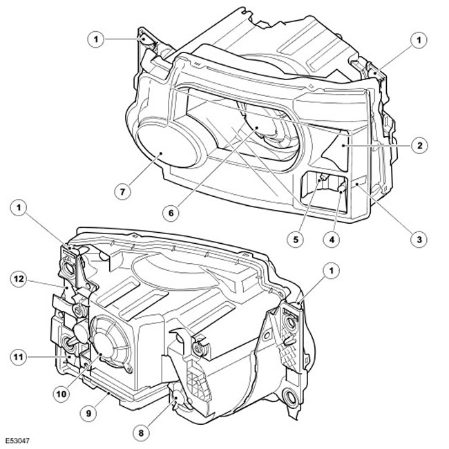
| Item name | Spare part catalog number | Description |
| 1 | - | Stop bar |
| 2 | - | Direction indicator |
| 3 | - | Side marker light (for USA only) |
| 4 | - | Clearance light |
| 5 | - | Side lights with tilting axis (excluding vehicles for the US market) |
| 6 | - | Adaptive xenon headlights low/high beam |
| 7 | - | Halogen high beam headlight |
| 8 | - | High beam headlight service hatch cover |
| 9 | - | Xenon headlight controller |
| 10 | - | Service hatch cover for low/high beam headlights |
| 11 | - | Cover of service hatch of side and side lights with tilting axis (not shown) |
| 12 | - | Turn signal service hatch cover (not shown) |
The new adaptive headlights are designed to improve visibility in various driving conditions. When turning, the adaptive headlights improve illumination of the part of the road where you will continue to drive. The position of the light beam in the horizontal plane is optimized automatically based on the position of the steering shaft and information from other sensors of the on-board system.
Adaptive headlights are supplied only with xenon lamps, the system includes a dynamic headlight levelling circuit, a description of which is given in the section "Headlight levelling correction".
Inside the headlight unit there is a module of a dual-mode xenon headlight, the position of which in the vertical and horizontal planes is regulated by the gearmotor electric motor in accordance with the road profile and turning radius. Only the spotlight with dual-mode xenon headlights can change its position, while the high-beam headlight with a halogen lamp remains stationary.
The adaptive headlights are controlled by their own controller, which is located at the bottom of the A-pillar, behind the CJB. The controller adjusts the position of the xenon spotlight vertically and horizontally depending on the operation of the cornering lights with a deflecting axis, which is requested by the adaptive headlights controller, but is controlled by the CJB.
How AFS works
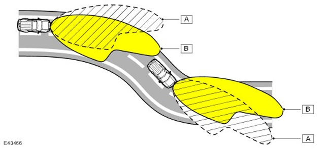
| A | Light distribution diagram for a conventional headlight |
| B | Light distribution diagram for adaptive headlights |
AFS Controller
The AFS controller is a dual-purpose device that also contains software for dynamic headlight leveling. The AFS controller is connected to the high-speed CAN bus and receives information from other on-board systems regarding the following parameters:
- Steering wheel angle - from steering wheel angle sensor
- Vehicle speed - from ABS controller
- Low beam headlight status - from instrument panel
- Suspension height - from air suspension controller
- Odometer readings are for diagnostic purposes only.
- Engine operation - from ECM
- Gear position - from the gearbox control unit or transfer case controller
- Engine Cranking - From ECM
- Outside/inside temperature - for diagnostic purposes only
The AFS system will also be activated when the light switch is in the AUTo position and the AFS controller receives a signal from the rain/light sensor to turn on the lights and a signal to confirm that the engine is running.
The AFS controller then begins monitoring input signals from other vehicle systems and controlling the headlights based on vehicle speed and turning radius.
AFS Controller C2193 Connector Contacts
| Contact No. | Description | Input signal/output signal |
| 1 | "Weight" | Input signal |
| 2 and 3 | Not used | - |
| 4 | CAN High Level Line | Input signal/output signal |
| 5 | CAN line low level | Input signal/output signal |
| 6 | Right headlight course drive gearmotor signal | Output signal |
| 7 | Right headlight course drive gearmotor signal | Output signal |
| 8 | Not used | - |
| 9 | Electric motor of the gear motor for the adjustment of the tilt of the right headlight 1 - "positive" (+) | Output signal |
| 10 | Electric motor of the gear motor for the adjustment of the right headlight tilt 1 - "negative" (-) | Input signal |
| 11 | Electric motor of the gear motor for the adjustment of the tilt of the right headlight 2 - "positive" (+) | Output signal |
| 12 | Electric motor of the gear motor for the adjustment of the tilt of the right headlight 2 - "negative" (-) | Input signal |
| 13 | Power supply from ignition 12V | Input signal |
| from 14 to 17 | Not used | - |
| 18 | Left headlight course drive gearmotor signal | Output signal |
| 19 | Left headlight course drive gearmotor signal | Output signal |
| 20 | Not used | - |
| 21 | Electric motor of the left headlight tilt correction gearbox 1 - "positive" (+) | Output signal |
| 22 | Electric motor of the left headlight tilt correction gearbox 1 - "negative" (-) | Input signal |
| 23 | Electric motor of the gear motor for the correction of the tilt of the left headlight 2 - "positive" (+) | Output signal |
| 24 | Electric motor of the left headlight tilt correction gearbox 2 - "negative" (-) | Input signal |
Operating modes
The AFS system can operate in four modes:
- Maneuvering mode
- Normal driving mode
- High speed driving mode
- Reverse mode
Normal driving mode is used when driving at a speed of 30-70 km/h. In normal driving mode, both xenon spotlights move in a ratio of 3:1, for example, during a left turn, the left spotlight turns by 3 degrees, and the right one by 1 degree. In this mode, the maximum angle of rotation of the course drive of the spotlight in the direction of the turn is 12 degrees.
The high-speed driving mode is used when driving at speeds over 70 km/h. In the high-speed driving mode, both xenon spotlights move in a ratio of 3:1, for example, during a left turn, the left spotlight turns 3 degrees, and the right spotlight turns 1 degree. In this mode, the maximum angle of rotation of the spotlight course drive in the direction of the turn is 10 degrees.
In reverse mode, the headlight directional drive is switched off when reverse gear is engaged. The AFS spotlights move to the central position and the tilting side lights, if switched on, are switched off. If the necessary conditions are met (i.e. the speed of the car exceeds 3 km/h), when reverse gear is disengaged, the AFS headlights move to a position corresponding to the steering wheel angle and the tilt-axis side lights turn on.
Adaptive xenon headlights
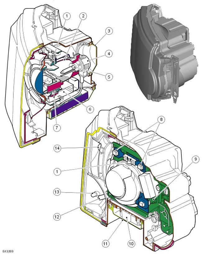
| Item name | Spare part catalog number | Description |
| 1 | - | Horizontal axis of the spotlight |
| 2 | - | Reflector |
| 3 | - | Service hatch cover |
| 4 | - | Xenon lamp connector DS2 |
| 5 | - | Xenon lamp DS2 |
| 6 | - | Gear motor for the horizontal adjustment of the adaptive headlight |
| 7 | - | Drive of the gear motor for horizontal adjustment |
| 8 | - | Vertical axes of the spotlight |
| 9 | - | Gear motor for the course drive for vertical adjustment of the adaptive headlight |
| 10 | - | Xenon headlight controller |
| 11 | - | Controller cover |
| 12 | - | Side light bulb with tilting axis (excluding vehicles for the US market) |
| 13 | - | Side light bulb |
| 14 | - | Turn signal lamp |
The design of the adaptive xenon headlight is similar to that of a non-adaptive xenon headlight. To perform the AFS function, a platform is added to the headlight unit, on which the AFS units are located. The remaining lights included in the xenon headlight unit are no different from those described earlier. The operation of the side lights with a deflecting axis on the adaptive headlight unit differs from the operation of the side lights when turning on a conventional xenon headlight unit.
The platform design has a radial bearing at the top and a thrust washer at the bottom, which provide support points for the horizontal axis of the xenon spotlight. The end of the lower axis of the headlight has splines, which are inserted into the splined hole of the electric motor of the AFS vertical adjustment gearbox. The platform is suspended on two flexible supports at the top, which provide attachment points for the vertical axis of the xenon spotlight, which allows the spotlight to be adjusted vertically. The lower part of the platform is attached to the electric motor of the AFS vertical adjustment gearbox.
The AFS gearmotor motors are DC motors, the power supply of which is controlled by the AFS controller. The AFS controller also provides the motor ground circuit.
The gearmotors include a potentiometer, which is connected by wires to the gold-plated contacts of the connector, which is connected to the AFS controller. Two wires connected to each gearmotor provide the AFS controller with feedback signals, which allows the position of the xenon spotlight to be adjusted with high accuracy.
For dynamic headlight tilt correction, the AFS controller uses signals from the front and rear suspension and controls the gear motor in the vertical plane. In addition, the AFS controller adjusts the illumination range by changing the headlight tilt, for which the speed signal received from the ABS controller is used.
Initiation procedure
The system initiation procedure consists of bringing the headlight axes into the correct position in the vertical and horizontal planes and is carried out after the AFS controller receives a signal to turn on the ignition.
Initiation of headlight leveling correction takes less than 3 seconds. Headlight leveling motors from their initial position (extreme upper, extreme lower, or anything in between) are brought to the extreme lower position and then to a horizontal position (the axis tilt is 0 degrees).
The AFS headlamp leveling drive is initiated in less than 1 second after the headlamp leveling motor is initiated so that the vertical axis of the headlamps is 0 degrees or less to avoid dazzling oncoming drivers. The headlamp leveling drive is initiated in less than 2.5 seconds. The right and left headlamp leveling drive gear motors first fully turn the headlamps inward from the 0° position, then fully turn them outward, and then return to the 0° position.
Emergency mode
In the event of an error in the operation of the AFS system, a visual indicator is turned on on the instrument panel, warning the driver of the malfunction. The indicator is turned on when the key is in position II in the ignition switch and does not stop glowing until the malfunction is corrected. The AFS indicator is also turned on if the steering shaft position sensor is faulty or if there is no vehicle speed signal.
When the AFS indicator comes on, it is not necessarily because the AFS system is faulty. The fault may be in another system that the AFS system depends on.
The AFS controller performs diagnostics on each system activation request. If an error is detected, the AFS controller suspends the system.
If the AFS system fails when the xenon projector is not pointed straight ahead, the AFS controller will attempt to set the xenon projector to the zero position. (straight ahead). If this adjustment is not possible, the AFS controller will lower the spotlight using the tilt correction motor gear motors to prevent blinding oncoming drivers.
The AFS controller software allows you to find your own internal faults. If you detect your own fault, the controller will set the headlights to zero and stop further control.
Fault codes can be scanned using the T4 diagnostic tool.
Side lights with tilting axis
NOTE: *US vehicles are not equipped with tilt-axle side lights
The lateral lights with a deflecting axis are designed to illuminate the direction of travel when turning at low speed. These lights are standard on vehicles with adaptive headlights. The design of the diffusers allows the light beam to be deflected by approximately 45 degrees from the vehicle axis. The lateral lights with a deflecting axis are controlled by the CJB.
The side light with a deflecting axis is built into the outer part of the headlight unit and is located in the same housing as the reflector and side marker light.
The tilt-axis side light uses a 35W H8 halogen bulb that fits into a socket that is wired to a connector on the headlight housing. The sockets are inserted into the headlight housing opening and turned until they lock. The bulb can be accessed through a removable cover on the rear surface of the headlight housing.
AFS headlight control
The control of the tilt-axle side lamp is based on the signal from the steering wheel position sensor, which is received by the AFS controller and the CJB. The AFS controller sends a request to turn on the tilt-axle side lamp to the CJB, which turns on the lamp bulb.
When driving at a speed of over 48 km/h, the tilt-axle side light comes on in the direction of the vehicle's turn when the steering wheel angle reaches 70 degrees. If the vehicle's turn is reduced, the tilt-axle side light goes off when the steering wheel angle reaches 50 degrees.
When driving at speeds below 48 km/h, the tilt-axle side light comes on in the direction of the vehicle's turn when the steering wheel angle reaches 245 degrees. If the vehicle's turn angle decreases, the tilt-axle side light goes off when the steering wheel angle reaches 225 degrees.
The cornering lamps with a tilt axis are controlled by the CJB. When the lamp is in the operating mode, the CJB reduces its brightness by sending pulse-width modulated (PWM) signals for approximately two seconds. When the lamp is switched off, the CJB reduces the lamp glow by reducing the voltage of the PWM signals.
Comments on this article