Contents: Side turn signal repeater lamp ⇩ Left multifunction steering column…⇩ Emergency alarm system ⇩ License plate lights ⇩ High-mounted brake light ⇩ Trailer exterior lighting ⇩ Diagnostics ⇩ Monitoring AFS Controller Faults ⇩ Central Junction Box (CJB) ⇩
Side turn signal repeater lamp
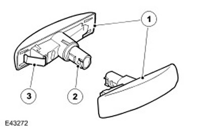
| Item name | Spare part catalog number | Description |
| 1 | - | Side turn signal repeater |
| 2 | - | Lamp holder |
| 3 | - | Spring lock |
The side turn signal repeaters are built into the driver's and front passenger's doors under the rear-view mirrors. The lights are inserted into the opening in the door panels, where they are held in place by spring clips. To remove the light, slide it back and then release the front edge of the light from the opening in the door. The side turn signal repeater sockets contain 5-watt bulbs without a base.
The side turn signal repeaters have the same function as the front and rear turn signals. They are activated by the left multifunction stalk and the hazard warning switch. The multifunction stalk only works when the ignition switch is in position II. (ignition on), the hazard warning switch operates in any circuit state. The side turn signal repeaters operate with an on/off cycle of 0.38 seconds. If one of the turn signal lamps fails, the remaining lamps will continue to operate at their normal frequency.
Left multifunction steering column switch
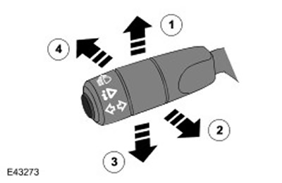
| Item name | Spare part catalog number | Description |
| 1 | - | Right turn signal lamp |
| 2 | - | High beam headlights alarm |
| 3 | - | Left turn signal lamp |
| 4 | - | Turning on high beam headlights |
The multifunctional steering column switch is located on the left side of the steering column and performs the following functions:
- Switching headlights from low beam to high beam and vice versa
- High beam headlights alarm
- Turning on the left/right turn signal
- Trip computer functions. For further information, contact the Information and Message Center (413-08)
Different circuits are also used to activate the direction indicators. When switching, the corresponding circuit is closed to ground, which is recognized by the CJB unit, which then turns on the required direction indicators.
Emergency alarm system
The hazard warning lights are controlled by a non-latching switch located in the centre of the instrument panel. The hazard warning lights can be switched on at any time, regardless of the position of the key in the ignition switch.
When the hazard warning lights are switched on, all front, rear and side direction indicators are switched on and operate in the mode described above. The left and right direction indicator indicators located on the instrument panel also flash. The direction indicators flash in the following mode: 380 ms - signal, 380 ms - pause. If the hazard warning light mode is active, it cancels any previously set state of the direction indicators.
If the vehicle is towing a trailer, its turn signals will also flash at the same rate as the vehicle's turn signals. The trailer indicator located on the dashboard will also flash. If the trailer turn signal bulb burns out, the trailer indicator will not flash.
The hazard warning lights may also be activated by a crash signal from the SRS module. This signal is received by the CJB, which activates the hazard warning lights. The hazard warning lights can be turned off by turning the ignition switch to position I or 0. They can also be turned off by a signal from the SRS module. For more information, refer to Air Bag and Safety Belt Pretensioner Supplemental Restraint System (SRS) (501-20B)
License plate lights
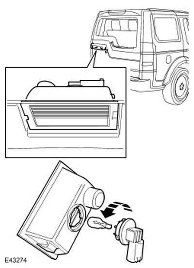
The two number plate lights are integrated into the tailgate handle and are located above the number plate in the upper tailgate flap. Each number plate light uses a 5W bulb without a socket. The lights are secured with clips in the upper tailgate handle and can be released with a small flat-blade screwdriver.
The registration plate lights are always on when the side lights or headlights are on.
High-mounted brake light
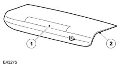
| Item name | Spare part catalog number | Description |
| 1 | - | High-mounted brake light |
| 2 | - | Frame |
The high-mounted brake light is located at the top of the tailgate. The brake light housing also houses the tailgate glass washer nozzle.
The brake light has a plastic housing with a red diffuser. The brake light is illuminated by light-emitting diodes (LED).
The high brake light is switched on simultaneously with the main light, when the ignition switch is in position II and the limit switch is closed when the brake pedal is pressed.
The high-mounted brake light can be activated by the anti-lock brake system when the hill descent control (HDC) function is active. The signal from the ABS closes the contacts of the relay, through which the electric power is supplied to the brake light. For more information, refer to Anti-Lock Control - Traction Control (206-09A)
Trailer exterior lighting
Depending on the market, the vehicle may be equipped with different types of sockets for connecting the trailer wiring. Details are provided in the Electrical Reference Library (ERL).
The Central Junction Box (CJB) continuously monitors the status of the direction indicator lamps and can determine if more than two lamps are installed (side turn signal repeaters are not controlled). If a trailer is detected (by number of lamps), then the trailer indicator on the dashboard will flash in the same rhythm as the vehicle's direction indicators.
If one or more of the direction indicators on a vehicle or trailer is faulty, the indicator will not flash, which is a sign to the driver that the bulb has burned out.
Diagnostics
Diagnostic bus connector (diagnostic connector) is located at the bottom of the instrument panel trim on the driver's side, under the steering column. Monitoring of various functions of the lighting system is performed by different systems of the car, which store fault codes in memory. These codes can be read using the T4 diagnostic tool or other similar scanner.
Monitoring AFS Controller Faults
The AFS controller monitors the AFS and dynamic headlamp leveling systems for malfunctions. The controller stores diagnostic trouble codes (DTCs) when the symptoms listed in the following table are detected.
| Description of malfunction symptoms that cause DTC codes to be recorded | Symptom of malfunction indicated by the customer | Possible reason |
| Malfunction of the communication line with the motor reducer of the right or left adaptive headlight | The headlight course drive system does not work | Break or short circuit to "ground" |
| Malfunction of the right or left adaptive headlight gear motor | The headlight course drive system does not work | Break or short circuit to "ground" |
| Malfunction of the right or left headlight tilt adjustment motor | The headlight leveling system does not work | Open or short circuit to ground or to 12V circuit |
| CAN bus failure | The headlight range control and headlight leveling systems are not working. Other vehicle systems are probably not working either. | Open or short circuit to ground or to 12V circuit |
Central Junction Box (CJB)
The CJB monitors the status of the lighting circuits, relays and switches. If a fault is detected, the CJB records a fault code that can be read using the T4 diagnostic tool or similar scanner.
Comments on this article