


Disassembly
1. Remove the crankshaft.
ENGINE KV6 - MODIFICATION K, Piston group, Crankshaft.
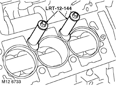
2. Remove the LRT-12-144 cylinder liner fasteners from the cylinder block.
3. Mark the position of the cylinder liners relative to the cylinder block.
4. With the help of a partner, position the cylinder block so that the pistons and cylinder liners can be removed.
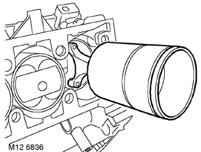
5. Carefully remove the cylinder liners with pistons from the cylinder block.
CAUTION: Mark the pistons and sleeves so that each piston will fit into its own sleeve.
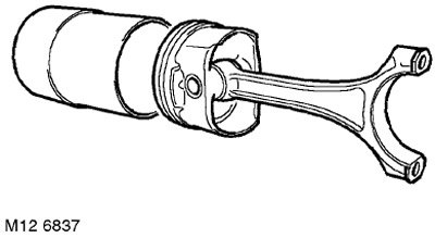
6. Remove the pistons from the liners. Arrange the liners in the order in which they were installed on the engine.
7. Place the connecting rod caps back onto the connecting rods and lightly tighten the retaining bolts.
8. Using a ring expander, remove the rings from the pistons and discard them.
9. Use the end of the broken old ring to clean the piston grooves from carbon deposits.
Examination
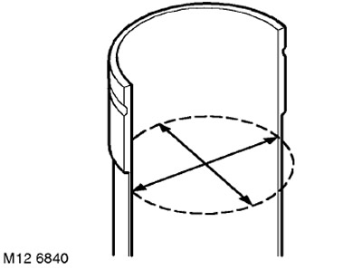
1. Cylinders: Measure wear in two planes at a distance of 65 mm from the upper end of the liner. The cylinder size group is marked on the outer surface of the liner.
CAUTION: Cylinder liners with excessively rubbed, worn, scratched or scored cylinder bore surfaces must be replaced. DO NOT ATTEMPT to hone or remove rubbing from the cylinder bore surface. If old liners are to be reused, retain the position marks when removing the liners.
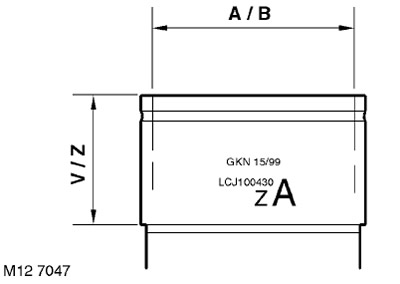
2. The cylinder diameter and seat height size group are determined by the manufacturer. The diameter size group (red, A or B, blue) and seat height group (V or Z) are applied to the outer surface of the liners together with the part number and color code. If the cylinder liner(s) is to be replaced, the new liner(s) must have the same seat height group as the one being replaced. Any cylinder diameter size group is supplied in two seat height size groups.
TECHNICAL SPECIFICATIONS, Engine - petrol KV6.
3. Check the pistons for damage and cracks.
NOTE: The designation of size groups A or B is stamped on the upper surface of the piston bottom.
4. Measuring the piston diameter: Measure the diameter of the piston skirt at a right angle to the axis of the piston pin, at a distance of 8 mm from the lower edge of the skirt.
(The text of the article was taken from the website: LRman.ru)
TECHNICAL SPECIFICATIONS, Engine - petrol KV6.
NOTE: Piston is supplied complete with connecting rod only.
CAUTION: Pistons must be installed in their original liners.
5. Insert the piston into the cylinder liner and measure the gap at a distance of 20 mm from the bottom of the liner.
TECHNICAL SPECIFICATIONS, Engine - petrol KV6.
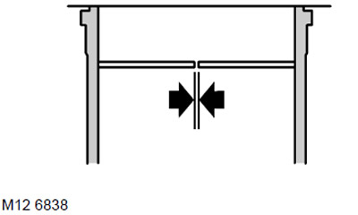
6. Piston ring gap: Insert new first and second compression rings into the cylinder, 20 mm from the top of the cylinder bore, and measure the ring gap.
TECHNICAL SPECIFICATIONS, Engine - petrol KV6.
ATTENTION: The rings must be in a plane perpendicular to the cylinder axis. The rings must be installed on the piston of the cylinder where they were checked.
7. Installing piston rings: Install the oil ring expander.
8. Turning the rings with the 'TOP' mark, or another mark, upwards, using pliers to spread the rings, put on the piston: oil scraper ring, 2nd compression ring and upper compression ring.
NOTE: The second compression ring is a scraper type.
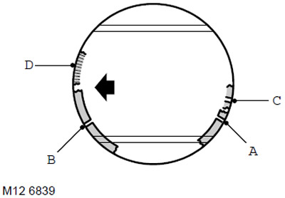
9. Check the freedom of movement of the rings in the grooves and move the locks A and B of the compression rings at an angle of 120 degrees to each other and away from the loaded part of the piston. The gap C of the oil scraper ring and the lock D of the ring expander are moved opposite each other, in a plane located at an angle of 30° to the axis of the piston pin.
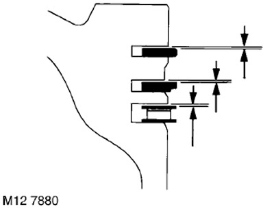
10. Check the axial clearances between the rings and piston grooves.
TECHNICAL SPECIFICATIONS, Engine - petrol KV6.
Assembly
1. Thoroughly wash the cylinder liners and their seats in the block.
2. Lubricate the cylinder bore, pistons and rings with clean engine oil, check that the ring locks are spaced apart from each other at the required angle.
3. Wipe the bearing beds in the connecting rods and in the connecting rod caps.
4. Place the LRT-12-204 ring crimping tool on the piston and insert the piston into its cylinder liner so that the arrow on the piston crown faces the front of the engine when installed on the engine. Repeat this operation with the remaining pistons.
CAUTION: Do not push the pistons too far down at this stage.
5. Remove the ring crimping tool.
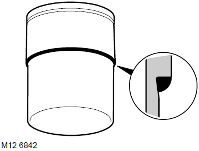
6. Apply a continuous bead of RTC 3347 sealant 2mm thick along the flange of each liner as shown.
7. Holding the sleeve perpendicular to the cylinder block, insert the sleeve into the socket until the seating belt stops against the block, paying attention to the fact that the arrow on the piston bottom should face the front of the engine.
8. To prevent the liners from shifting, install the LRT-12-144 fasteners on the cylinder block and secure them with the cylinder head bolts. The base of the cylinder liner fasteners should not protrude above the cylinder bore.
9. Install the crankshaft.
ENGINE KV6 - MODIFICATION K, Piston group, Crankshaft.
Comments on this article