Dismantling
1. Remove the cylinder head gaskets.
KV6 ENGINE - K MODIFICATION, Piston group, Left cylinder head gasket.
KV6 ENGINE - K MODIFICATION, Piston group, Right cylinder head gasket.
Disassembly
1. Left cylinder head: Remove the 3 bolts securing the left rear timing belt cover and remove the cover.
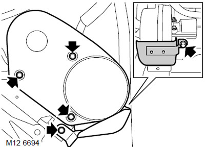
2. Right cylinder head: Remove the 2 bolts securing the heat shield to the rear timing belt cover on the right cylinder head.
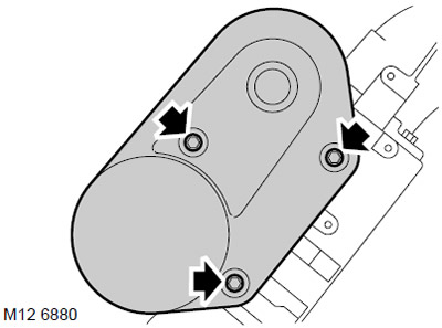
3. Right cylinder head: Remove the 3 rear timing belt cover bolts on the right cylinder head and remove the cover.
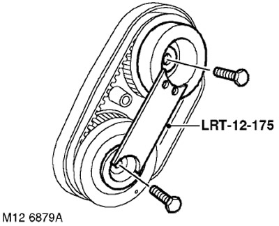
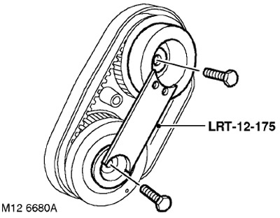
4. Install the LRT-12-175 tool on the rear gears, unscrew and discard the bolts securing the gears to the camshafts.
5. Remove the gear wheels, timing belt and tool LRT-12-175 as an assembly.
6. Remove the tool LRT-12-175 from the gears and remove the timing belt from the wheels. Dispose of the timing belt.
7. Turn out spark plugs.
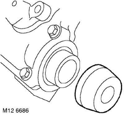
8. Remove and discard the exhaust camshaft oil seal from the cylinder head.
NOTE: Drawing shown is for right cylinder head.
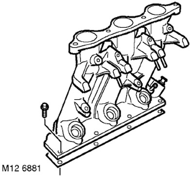
9. Consistently loosen and unscrew the 7 bolts securing the intake manifold to the cylinder head, remove the manifold and discard the gasket.
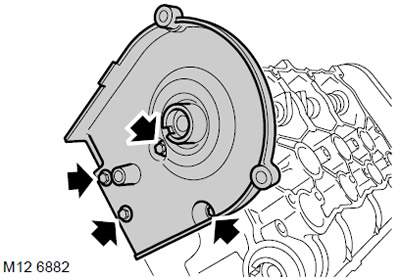
10. Turn away 4 bolts of fastening of a back cover of a forward timing belt to the right head of cylinders and remove a cover.
NOTE: Left cylinder head rear belt cover shown.
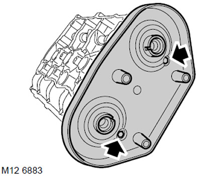
11. Turn away 2 bolts of fastening of a back cover of a back belt of GRM to a head of cylinders and remove a cover.
NOTE: Left cylinder head rear belt cover shown.
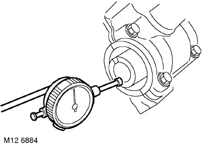
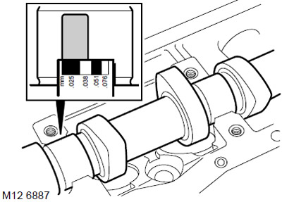
12. Check the end play of the camshafts using a dial indicator.
TECHNICAL CHARACTERISTICS, Engine - petrol KV6.
WARNING: If the end play exceeds the allowable value, then recheck with a new camshaft (camshafts). If end play is still too high, replace cylinder head assembly with camshaft cover.
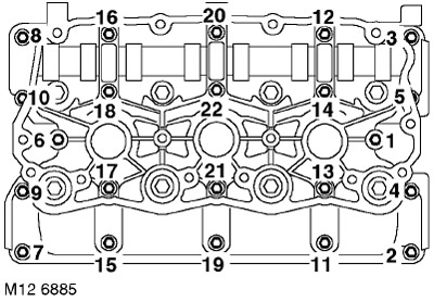
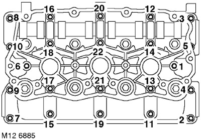
13. Gradually, in the sequence shown in the figure, loosen the 22 camshaft cover bolts so that the valve springs are completely unloaded.
14. Remove the camshaft cover.
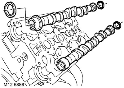
15. Remove the camshafts and discard the camshaft seals.
NOTE: Exhaust camshafts are color coded orange.
16. Using a magnet, remove 12 hydraulic lifters from the cylinder head.
CAUTION: The hydraulic lifters must be laid out in the order in which they were installed on the cylinder head. The maximum possible cleanliness must be observed when working with hydraulic lifters. Failure to comply with these requirements may result in engine failure.
17. Measure the outside diameter of the hydraulic lifters.
TECHNICAL CHARACTERISTICS, Engine - petrol KV6.
NOTE: The measurement is taken in the middle chord of the compensators.

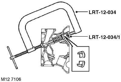
18. Using the LRT-12-034 cracker with the LRT-12-034/1 tip, compress the valve springs, remove two crackers, release the spring and remove the LRT-12-034 cracker.
19. Remove the valve spring with the top plate.
20. Remove the valve from the cylinder head.
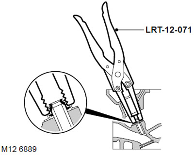
21. Remove the oil seal using the LRT-12-071 puller. Dispose of the oil seal.
22. Do the same on the remaining valves, laying out the removed parts in the order in which they were on the cylinder head.
Examination
1. Wipe the camshafts, the bearing surfaces of the camshaft journals in the bed, the mating surfaces of the bed of the camshafts and the cylinder heads.
2. Check the condition of the camshafts. If they are scratched, dented, or excessively worn, replace the camshafts.
3. Lay camshafts in a head of cylinders and impose a strip of a deformable caliber on each of necks.
WARNING: Do not interchange the intake and exhaust shafts. The camshafts are color coded: ORANGE - intake camshaft, BLUE - exhaust camshaft.
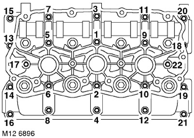
4. Install the camshaft cover and gradually, in the sequence shown in the figure, tighten the bolts to a torque of 10 Nm. Do not rotate camshafts.
5. In the sequence shown in the figure, loosen and remove the camshaft cover bolts. Remove the camshaft cover from the cylinder head.
6. Measure the widest part of each gauge strip.
TECHNICAL CHARACTERISTICS, Engine - petrol KV6.
7. If the gap is greater than the allowable, then install new shafts and repeat the check. If the clearance is still too large, replace the cylinder head.
8. With a cloth soaked in oil, remove all traces of a deformable caliber from the necks.
9. Clean the sealing surfaces of the cylinder heads. Wipe the mating surfaces of the intake and exhaust manifolds.
CAUTION: Do not use a metal scraper.
10. Clear a deposit from a deposit the lower plane of a head of cylinders.
11. Blow out the oil channels and channels of the cooling system.
12. Check the cylinder head for damage, paying special attention to sealing surfaces.
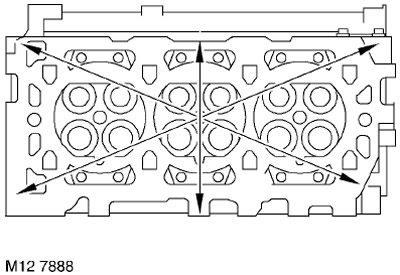
13. Check the plane of the cylinder head for warping by laying a straightedge along the directions shown in the figure.
TECHNICAL CHARACTERISTICS, Engine - petrol KV6.
14. Check up height of a head of cylinders.
TECHNICAL CHARACTERISTICS, Engine - petrol KV6.
NOTE: It is acceptable to grind the underside of the cylinder heads provided the head height remains within acceptable limits.
15. Check the condition of the valve springs and measure the free height of the springs.
TECHNICAL CHARACTERISTICS, Engine - petrol KV6.
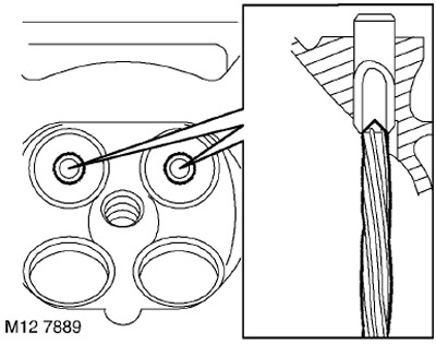
16. Use a 6 mm reamer to remove carbon from the exhaust valve guides. The reamer is inserted into the guide from the side of the lower plane of the head.
17. Remove carbon from intake valve guides, intake and exhaust valves, and valve seats. After completing the descaling procedure, blow out the head to remove all particles.
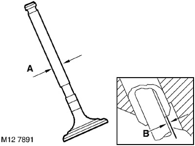
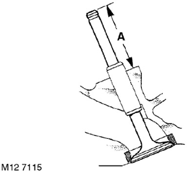
18. Measure and record the stem diameters 'A' of the old valves, replace the valve if the stem diameter is less than acceptable.
TECHNICAL CHARACTERISTICS, Engine - petrol KV6.
19. Using the procedure below, measure clearances 'B' between the intake and exhaust valve stems and their guides.
20. Insert all valves into their respective bushings.
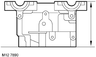
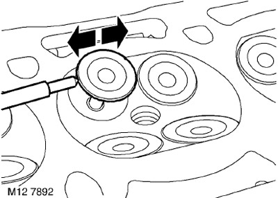
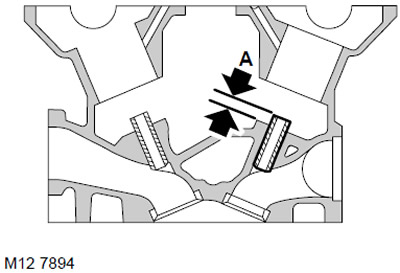
21. Pull the valve disc 15 mm up and install the dial indicator as shown in the figure.
22. Move the valve plate to the front of the cylinder head and set "zero" indicator, making sure that the indicator leg remains pressed against the plate.
23. Move the valve to the rear of the cylinder head and read indicator 'B'.
TECHNICAL CHARACTERISTICS, Engine - petrol KV6.
24. Remove the valves and arrange them in the same order.
25. Replace valves and valve guides if necessary.
26. In order to remove the guide bushings, lay the cylinder head flat on wooden blocks.
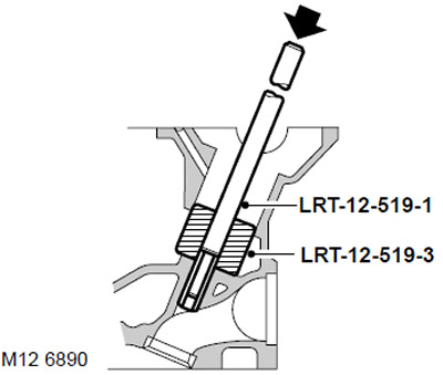
27. Insert drift LRT-12-519-3 into the pusher socket and knock out the bushing using the LRT-12-519-1 drift.
CAUTION: Lay out the valve guides in the same order as they were on the assembled engine.
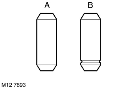
28. Determine the type of bushings installed: 'A' - Factory assembled 'B' - Replaced in service.
WARNING: Factory installed bushings 'A' must be replaced with repair bushings 'B'.
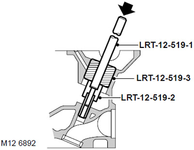
29. Install the valve guide into the guide seat, with the groove toward the valve seat, and install the LRT-12-519-2 stopper onto the guide.
CAUTION: When replacing bushings, the cylinder head and bushing must be at room temperature.
30. Install the LRT-12-519-3 kapron mandrel into the compensator socket and drive the sleeve with the LRT-12-519-1 mandrel until the limiter reaches the surface of the cylinder head.
31. Check that protrusion 'A' of the plugged bushing is 6.0 mm.
32. Check the condition of the valve seats and those valves that are to be reused.
33. Replace valve seats if necessary.
CAUTION: Be careful when removing the seats to avoid damaging the seating surface.
34. Cool the new seats in liquid nitrogen and immediately press them into the cylinder head without stopping during pressing.
CAUTION: Do not heat the cylinder head. Saddles after chamfering should not protrude above the lower plane of the cylinder head
35. Cut the bevels of the saddles with a special cutter with a pilot, while ensuring the following angles of inclination:
- 15°- First cut
- 45°- Final cut with deburring
- 60°- Undercutting to obtain the desired bevel width
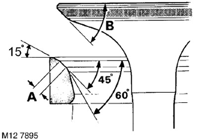
36. Check the width of the chamfer of the valve and its angle of inclination:
- Chamfer Width 'A' - Inlet = 1.2mm; Outlet = 1.6mm
- Valve Angle 'B' - Inlet &Exhaust = 45°
37. Lappe the valves to the seats using lapping paste.
38. Apply a thin layer of Prussian blue to the bevel of the valve seat, insert the valve into the guide and press it several times without rotating. Remove the valve and check the uniformity and position of the fit by looking at the imprint. The ink should be printed along the centerline of the bevel. a: The imprint is closer to the stem (high), deepen the slot at a 60°angle and restore the width of the seat bevel. b: The print is closer to the edge of the plate (low): Deepen the 45°slot and restore the seat bevel width. Lap the valve in and recheck its fit to the seat.
39. Check valve stem protrusion 'A'.
TECHNICAL CHARACTERISTICS, Engine - petrol KV6.
CAUTION: If the valve stem protrudes more than allowed, install a new valve and check the stem protrusion again. If this measure does not help, then replace the valve seat.
40. Wash the valve springs and lubricate the valves.
Assembly
1. Lubricate new valve stem seals with clean engine oil.
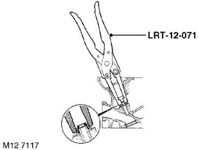
2. Using the LRT-12-071 mandrel, install new valve stem seals.
3. Insert valves.
4. Install the spring and upper spring plate.
5. Install the LRT-12-034 dryer with the LRT-12-034/1 tip on the valve disc and compress the spring.
6. Install crackers.
7. Release the valve spring and remove the LRT-12-034 cracker.
8. Through a wooden block, hit the end of the valve stem two or three times so that the crackers take their working position in the grooves of the stem.
9. Wipe the hydraulic lifters thoroughly and lubricate them with clean engine oil. Install the hydraulic lifters in the cylinder head, in their original places.
10. Check that the mating surfaces of the cylinder head and camshaft covers are clean and dry.
11. Lubricate the camshafts with clean engine oil.
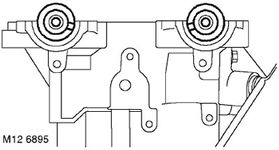
12. Lay the camshafts in the cylinder head so that the grooves for the gear wheels are directed towards the middle of the engine, as shown in the figure.
WARNING: Do not interchange the intake and exhaust shafts. The camshafts are color coded: ORANGE - intake camshaft, BLUE - exhaust camshaft.
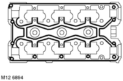
13. Apply continuous, thin bead of STC 4600 Sealant at the locations shown in the illustration. Spread the sealant in a thin layer over the surface with a roller trowel.
WARNING: Assembly of prepared parts must be done immediately to prevent contamination of surfaces with applied sealant.
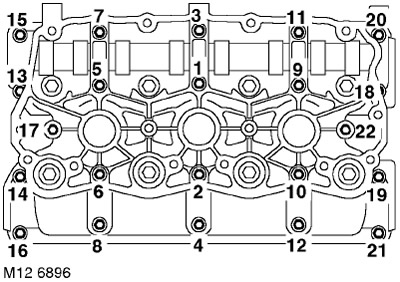
14. Install the camshaft cover, screw in and gradually tighten the bolts to 10 Nm in the sequence shown in the figure.
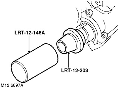
15. Keeping in mind that the front oil seals are black and the rear oil seals are red, install new oil seals using LRT-12-203 and LRT12-148A.
CAUTION: The seals must be installed dry. Do not use tool LRT-12-148 to install oil seals.
16. Clean the timing belt rear cover bolts and apply STC 50552 sealant to the first three threads.
17. Install the rear covers of the rear timing belts on the cylinder head, screw in the bolts and tighten them to a torque.
18. Screw in the spark plugs.
19. Clean the rear camshaft gears and their seats on the camshafts.
WARNING: If sintered gears (powder metallurgy technology), have been in contact with oil for a long time, then, before installation, they must be soaked in a solvent and then washed in a pure solvent. The porous structure of the sintered material absorbs oil, which, if released, will contaminate the timing belts.
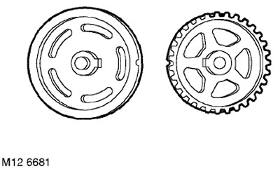
20. Lay the reversed gears on a flat surface with the marks turned as shown.
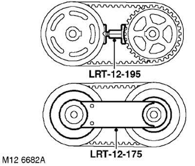
21. Put the timing belt on the gears, keeping the alignment marks aligned.
22. Install the LRT-12-195 tool between the gears, turn the tool nut until the belt is sufficiently tensioned.
23. Turn over the gear wheels with the belt and install the tool LRT-12-175 on the gear wheels.
24. After checking the alignment of the alignment marks, remove the LRT-12-195 tool that was between the wheels.
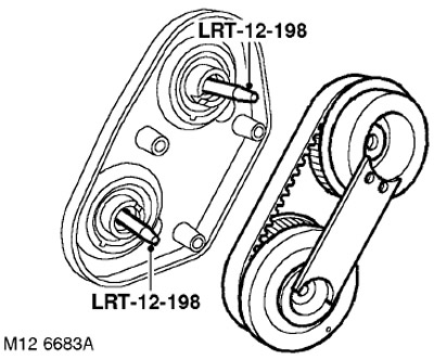
25. Install guide pins LRT-12-198 into the end of each of the camshafts.
26. Using guide pins LRT-12-198, put the gears on the camshafts.
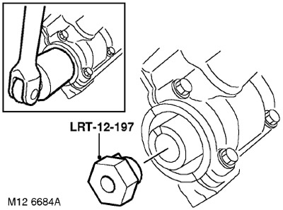
27. Screw special bolt LRT-12-197 into the front end of the exhaust shaft.
28. With the help of a partner, by installing a 30 mm socket on the LRT-12-197 special bolt, rotate the camshaft until the protrusions on the gears align with the grooves of each of the camshafts.
29. Unscrew the guide pins LRT-12-198 and screw in new bolts for fastening the gear wheels.
30. Tighten the gear wheel bolts:
- Stage 1: 27 Nm
- Step 2: Turn 90°
31. Remove tool LRT-12-175 from gears.
32. Remove special bolt LRT-12-197 from the front of the exhaust camshaft.
NOTE: It is possible that after replacing the front or rear timing belt and setting the crankshaft pulley to the 'SAFE' position, the position marks on the rear cogwheels will no longer align. Such a mismatch is acceptable provided that the belt replacement procedure was carried out without errors.
33. Install the rear timing belt cover and tighten the mounting bolts to 9 Nm.
Installation
1. Install the cylinder head gaskets.
KV6 ENGINE - K MODIFICATION, Piston group, Left cylinder head gasket.
KV6 ENGINE - K MODIFICATION, Piston group, Right cylinder head gasket.
Comments on this article