Dismantling
1. Remove the cylinder head gaskets.
KV6 ENGINE - K MODIFICATION, Piston group, Left cylinder head gasket.
KV6 ENGINE - K MODIFICATION, Piston group, Right cylinder head gasket.
2. Remove the oil pump gasket.
KV6 ENGINE - K MODIFICATION, Piston group, Oil pump overhaul.
3. Take out a back epiploon of a cranked shaft.
KV6 ENGINE - MODIFICATION K, Piston group, Replacing the crankshaft rear oil seal.
4. Remove the engine tray bottom cover.
KV6 ENGINE - MODIFICATION K, Piston group, Lower oil pan cover.
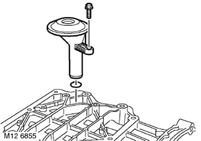
1. Loosen the bolt securing the oil receiver with strainer, remove the oil receiver and discard the O-ring.
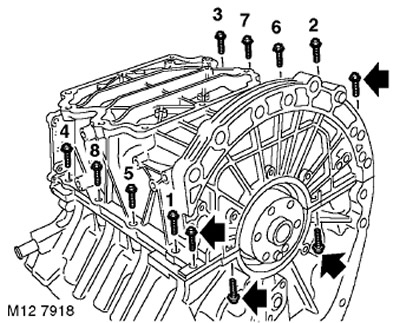
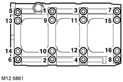
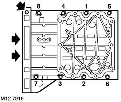
2. In the sequence shown in the figure, unscrew and dispose of 8 M8 bolts securing the upper part of the pallet to the cylinder block.
3. Turn out the remained M8 bolts and 2 M6 bolts with which the top part of the pallet fastens to the block of cylinders.
4. Remove the pallet.
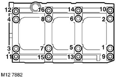
5. In the sequence shown in the figure, unscrew and dispose of the 16 bolts securing the integral main bearing cap to the cylinder block.
NOTE: The short bolts are on the outside of the main bearing cap.
6. Release the main bearing cap from the guide pins and remove the bearing cap from the engine.
7. Remove the lower main shells and two thrust washers from the integral bearing cap, arrange the bearings in the order in which they were on the engine, and discard the half washers.
8. Temporarily screw in the front pulley bolt.
9. Remove 4 fitting bolts (bolt that simultaneously acts as a pin) and remove the covers from the connecting rods of the 1st and 2nd cylinders. Lay out the covers in the order in which they were installed.
NOTE: Number stamped under the connecting rod cap bolt. is the code for the size group of the connecting rod bearing bed. The number stamped on the connecting rod body is the cylinder number, and the letter is the weight group code.
CAUTION: Do not remove LRT-12-144 fasteners unless pistons and connecting rods are to be removed.
10. Move the connecting rods away from the crankshaft journals.
11. Remove the connecting rod bearings from the connecting rod and from the connecting rod cap.
12. Turn the crankshaft by the pulley mounting bolt and unscrew the bolts securing the remaining connecting rod caps. Remove the connecting rod caps and remove the liners from them. Lay out the connecting rod caps in the order they were installed on the engine.
13. Remove a cranked shaft, take out the top radical loose leaves and persistent half rings from the block of cylinders. Dispose of the thrust half rings.
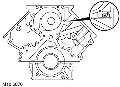
14. Selection of main bearings: copy the letter code of the main bearing size group from the front wall of the cylinder block. The letters are arranged according to the numbers of the main necks, from left to right: the first letter refers to the first (front) root neck.
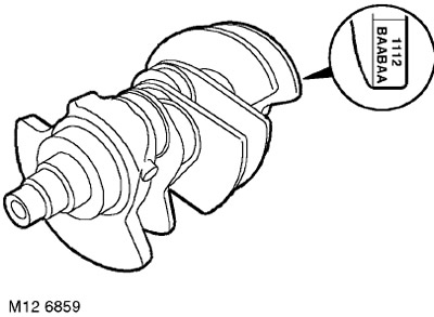
15. Rewrite the letter code of the size groups of the main bearings, stamped on the counterweight of the crankshaft. The first letter on the left refers to the liners of the first main journal and, further, in order.
Examination
1. Measure the diameter of the crankshaft main journals.
2. The resulting value must be within tolerance. If not, then the crankshaft should be replaced.
TECHNICAL CHARACTERISTICS, Engine - petrol KV6.
3. Select main bearings for installation on the engine, using the appropriate tables in the section on general information.
TECHNICAL CHARACTERISTICS, Engine - petrol KV6.
4. The thickness of the main bearing is indicated by a colored mark on its edge.
TECHNICAL CHARACTERISTICS, Engine - petrol KV6.
5. Crankshaft journals: Measure the diameter of the crankshaft journals and replace the crankshaft if the measurements are not within tolerance.
TECHNICAL CHARACTERISTICS, Engine - petrol KV6.
6. Determine the thickness of the connecting rod bearing by the colored mark on its edge.
TECHNICAL CHARACTERISTICS, Engine - petrol KV6.
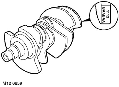
7. Selection of connecting rod bearings: Write down the letter code of the size group of the connecting rod journals, located on the rear counterweight. The first letter on the left refers to the bearings of the first crankpin and, further, in order.
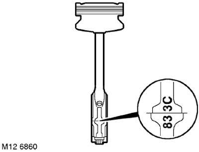
8. Rewrite the digital code (7, 8 or 9) size group of connecting rod bearings, embossed on the connecting rod cap.
9. Selection of connecting rod bearings: The necessary connecting rod bearings are selected according to the tables in the section dedicated to general data.
TECHNICAL CHARACTERISTICS, Engine - petrol KV6.
10. Check that all threaded holes are clean and dry. Remove the remaining sealant from the threaded part of the oil receiver mounting bolt and from the threaded hole for the bolt.
WARNING: Tap (for thread cleaning) use is prohibited.
11. Check that the integral main bearing bed locating pins are in place and that the pin holes are clean and dry.
12. Check up a branch pipe of system of cooling on the block of cylinders regarding signs of a leak or corrosion and if necessary replace. Apply sealant STC 50554 to the new pipe installed in the cylinder block.
13. Wipe the bed of the main bearings in the cylinder block.
14. Wipe the main and connecting rod journals of the crankshaft. Wipe the bed liners in the connecting rods and in the connecting rod caps.
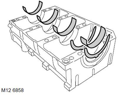
15. Install the selected main bearings in the bed. Groove liners are installed in the cylinder block, flat liners are placed in the main bearing cap.
16. Establish on the block of cylinders new persistent half rings.
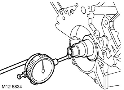
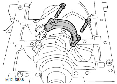
17. Establish a leg of the dial indicator on an end face of a cranked shaft, as it is shown in drawing. Slide the crankshaft back away from the indicator, install "zero" indicator, move the crankshaft forward and read the reading.
TECHNICAL CHARACTERISTICS, Engine - petrol KV6.
ATTENTION: If the axial play exceeds the allowable value, then the crankshaft must be replaced.
Assembly
1. Install the selected connecting rod bearings in the connecting rod and caps.
2. Lubricate the connecting rod journals with clean engine oil. While holding the crankshaft so that the connecting rod journals are in a horizontal plane, lay the crankshaft in bed.
3. Carefully slide the connecting rod onto the neck, install the connecting rod cover, paying attention to the fact that the mounting grooves in the cover and in the body of the connecting rod should be on opposite sides and slightly tighten the connecting rod bolts.
4. Tighten the fitting bolts:
- Stage 1: 20 Nm
- Step 2: Turn 45°
5. Moisten a lint-free cloth with solvent and wipe the mating surfaces of the main bearing cap and cylinder block.
6. Lubricate the thrust washers with clean engine oil and install them in the main bearing cap, grooves facing out.
7. Install the main bearing cap and check that all bearings are in place.
8. Screw in new bearing cap bolts, remembering that longer bolts are placed on the inner row, and tighten them:
- Stage 1: 20 Nm
- Step 2: Turn 90°
9. Having moistened a rag that does not give threads with a solvent, wipe the mating surfaces of the pallet and cylinder block.
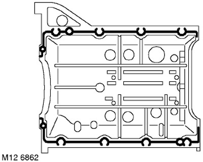
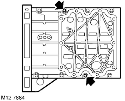
10. Apply a continuous bead of STC 50550 Sealant to the sump along the contours shown in the figure and spread it in a thin layer using a roller trowel.
WARNING: Assembly of prepared parts must be done immediately to prevent contamination of surfaces with applied sealant.
11. Install two M8 threaded guide pins into the cylinder block as shown.
12. Establish the pallet on the block of cylinders.
13. Screw in and lightly tighten the 6 M8 bolts, unscrew the guide pins, screw in and lightly tighten the remaining 2 M8 bolts.
14. In the sequence shown in the figure, tighten the bolts to 25 Nm.
15. Screw in the remaining M8 bolt and tighten it to 25 Nm.
16. Screw in 2 bolts M6 and tighten them with a torque of 9 Nm.
17. Wipe the oil pickup tube and mating surfaces.
18. Lubricate a new O-ring with clean engine oil and fit onto the oil pickup tube.
CAUTION: O-ring part number LYX 000210L must be installed.
19. Apply sealant STC 50552 to the threaded part of the oil receiver mounting bolt.
20. Install the oil pick-up tube, screw in the bolts and tighten them to a torque of 25 Nm.
21. Clean the oil pump, the crankshaft oil seal seat in the pump housing and the mating surface of the cylinder block, check that the threaded sockets in the cylinder block are clean and dry.
22. Wipe the sealing surface of the crankshaft nose.
Installation
1. Install the oil pump gasket.
KV6 ENGINE - K MODIFICATION, Piston group, Oil pump overhaul.
2. Replace the engine tray bottom cover.
KV6 ENGINE - MODIFICATION K, Piston group, Lower oil pan cover.
3. Establish a back epiploon of a cranked shaft.
KV6 ENGINE - MODIFICATION K, Piston group, Replacing the crankshaft rear oil seal.
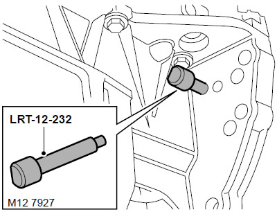
4. Rotate the crankshaft until the LRT-12-232 pin enters the oblong hole in the drive plate through the hole in the sump located at the edge of the sump.
ATTENTION: Make sure that the finger enters the oblong hole. Do not use the arrow molded on the oil pump housing as a setting mark. Do not remove your finger from the drive plate until the timing belts are installed.
5. Install the cylinder head gaskets.
KV6 ENGINE - K MODIFICATION, Piston group, Left cylinder head gasket.
KV6 ENGINE - K MODIFICATION, Piston group, Right cylinder head gasket.
Comments on this article