Contents: Control module - 3rd and 4th…⇩ Electrohydraulic pump ⇩ Mechanical hydraulic pump - 3rd…⇩ Mechanical hydraulic pump - 4th…⇩ Bypass valve ⇩ Receiver ⇩ Wet Clutch Disc Kit ⇩
NOTE: 3rd generation variant shown.
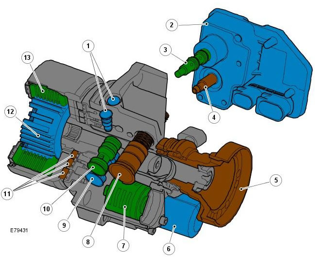
| Pos. | Spare part number | Name |
| 1 | - | Check valves - outlet side |
| 2 | - | Active Clutch Module |
| 3 | - | Check valve / axial solenoid valve |
| 4 | - | Oil pressure and temperature sensor |
| 5 | - | Input shaft |
| 6 | - | Electrohydraulic pump |
| 7 | - | Oil filter |
| 8 | - | Receiver |
| 9 | - | Check valve - inlet side |
| 10 | - | Combined check and bypass valve |
| 11 | - | Ring-shaped piston |
| 12 | - | Inner coupling hub with splines for outer hub. |
| 13 | - | Inner and outer discs of a wet clutch |
The active clutch provides the benefits of a permanent all-wheel drive system with the efficiency and economy of a non-permanent system. The clutch, located between the differential and the propeller shaft, is an autonomous unit that performs mechanical, hydraulic and electronic functions to distribute drive force between the front and rear axles, with transparent automatic control.
The active clutch performs the following functions:
- Electronic torque control.
- Quick engagement based on required traction force.
- Rapid shut-off to ensure that its operation does not distort wheel speed signals and disrupt the operation of the electronic stability control system; this is especially important on very low friction surfaces.
- Pre-engagement from standstill to minimise wheel slip.
- There are no counteracting forces when maneuvering and parking the car.
- No sensitivity to chassis dynamometer brake testing.
Active Clutch 4th Generation - Vehicles from 2009 model year:
- The 4th generation clutch does not have the differential speed driven pump used on the 3rd generation clutch, but does have a higher capacity electric axle pump and a high pressure accumulator.
- The throttle follower valve and pressure sensor on the 3rd generation clutch have been replaced by a pressure reducing follower valve.
- The torque limiter pressure reduction valve on the 3rd generation clutch is replaced by an electronic control valve and control software.
The 4th generation active clutch has the following improvements over the previous 3rd generation clutch:
- Reduced base torque at high differential speeds.
- Torque activation now occurs depending on the differential speed.
- Precise control of torque limiter.
- The energy stored in the pressure accumulator results in a reduction in the maximum current in the electric pump and a faster response.
Control module - 3rd and 4th generation couplings
The control module, mounted on the active clutch housing, forms a single unit with the control valve/axial solenoid valve. By analyzing information from other modules and sensors in the vehicle, the control module regulates the axial solenoid valve, controlling the hydraulic fluid pressure acting on the clutch discs. Some of the modules and sensors that the control module communicates with are listed below:
- Elements connected with wires:
- Check valve / axial solenoid valve
- Electrohydraulic pump
- Oil pressure and temperature sensor
- High-speed CAN bus
- Engine Control Module
- Anti-lock brake system/traction control system module
- Traction control switch
- Vehicle Yaw Rate Sensor
- Steering wheel angle sensor
The axial solenoid valve continuously regulates the output parameters of the control valve using a PWM (pulse width modulated) signal. The pressure of the working fluid acting on the clutch discs determines the amount of torque supplied to the rear axle.
The active clutch has built-in oil pressure and temperature sensors, allowing the control module to accurately control torque transmission under all operating and environmental conditions. Using these signals, the control module applies strategies to protect the clutch from overheating; in extreme cases, to protect the clutch from damage, the clutch disengages if the hydraulic fluid temperature exceeds 105°C. Normal clutch operation resumes when the temperature drops below 101°C.
The control module has an integrated diagnostic system that continuously monitors the active clutch system and its input and output signals. If the control module detects a fault, a DTC (Diagnostic Trouble Code) is generated. The DTC is accessed using the diagnostic system specified by Land Rover.
Electrohydraulic pump
When driving on very low friction surfaces, such as wet grass, snow or ice, initial wheel spin and loss of traction may occur. With an active clutch, the wheels may turn almost 60 degrees before torque can be transmitted through the clutch.
To counteract this phenomenon, Land Rover has developed a unique high-pressure pre-charge function on the 3rd generation clutches, which activates the hydraulic circuit as soon as the engine is started. In effect, an electrically driven hydraulic pump is designed to maintain a potential torque of 500 Nm in the clutch. (This torque potential has been increased to 1,500 Nm for the 4th generation clutch.).
Vehicles with Terrain Response have the added benefit of being able to vary the pre-charge level to provide optimum traction on different surfaces. The pre-charge level varies depending on the Terrain Response mode, for example:
- When Terrian Response is set to "Special Programs Off", which is the same as normal operation for vehicles without Terrian Response, when the vehicle is moving off from a standstill in a straight line, the 3rd generation clutch is programmed to deliver 500 Nm of torque to the rear axle and the 4th generation clutch is programmed to deliver 1,500 Nm of torque. This strategy minimises loss of traction when moving off, regardless of the road surface/terrain. As the vehicle accelerates, the clutch pressure is reduced to reduce fuel consumption.
- By monitoring the steering angle, the clutch can be programmed to transmit no torque through it. This prevents the clutch from locking up when maneuvering the vehicle at low speeds and at sharp steering angles.
- In Grass/Gravel/Snow mode, the clutch is programmed to maintain a pre-charge condition until much higher speeds are reached. These same conditions apply even when the vehicle is driven at low speeds and at sharp steering angles, since traction takes priority over clutch lock on low-friction surfaces.
For more information, refer to the chapter: Ride and Handling Optimization (204-06 Ride and Handling Optimization, Description and Operation).
Mechanical hydraulic pump - 3rd generation couplings
The propeller shaft connects to the front clutch disc assembly (primary), the rear clutch disc assembly connects to the differential pinion (secondary). The swash plate with 6 hydraulic rollers also connects to the differential pinion. When there is no speed difference between the input and output sides of the clutch, the rollers do not work.
However, when the front and rear axles begin to rotate at different speeds, the swash plate rotates relative to the rollers, which creates hydraulic pressure. This pressure serves to force the opposing clutch discs into alignment, thereby increasing the torque transfer to the rear axle. As the speed difference between the axles increases, the hydraulic pressure further pushes the clutch discs toward each other to increase the torque transfer to the rear axle.
The control valve/axial solenoid valve controls the amount of pressure acting on the clutch plates and therefore the amount of torque transmitted to the rear axle. Tight manufacturing tolerances and extremely low component wear guarantee precise torque control throughout the entire service life of the vehicle.
Mechanical hydraulic pump - 4th generation couplings
The 4th generation clutch does not use a swash plate to mechanically increase the hydraulic pressure, but instead uses a new hydraulic pump to generate the hydraulic pressure and bring the clutch discs together. The removal of the swash plate increases the overall surface area of the clutch discs, which in turn reduces the hydraulic pressure required. The pressure required to deliver 1,500 Nm of torque has been reduced from 100 bar for the 3rd generation clutch to 40 bar for the 4th generation clutch.
The input and output positions on the 4th generation coupling remain the same as on the 3rd generation coupling as described above.
Bypass valve
On surfaces with very low friction, a braking torque of the driveline may be generated, for example:
- reverse torque when braking engines; or
- forced movement of the propeller shaft by the front wheels.
This can affect the speed of the rear wheels, preventing the true ability of the rear wheels to grip because the wheel speed signal is distorted. To eliminate this possibility, immediate disengagement of the clutch is provided when the stability control system is activated. For this purpose, a bypass valve is used, which immediately reduces the pressure in the system to the nominal level.
To balance the 4 bar base pressure (see below for details), the 3rd generation clutch uses a large disc spring to spread the clutch discs apart to prevent torque transmission through the clutch. Even at 0°C, torque transmission drops from 300 Nm to zero within 10 ms. However, the 4th generation clutch does not require a disc spring to spread the clutch discs apart because there is no base pressure in the clutch to push the discs together.
Receiver
The greater the distance the clutch discs must travel to engage, the longer it takes to displace the hydraulic fluid needed to build up pressure and transmit torque. To counteract this, the 3rd generation clutch is equipped with a reservoir. It maintains a nominal pressure of 4 bar in the hydraulic circuit. Although this pressure is insufficient to ensure the transmission of significant torque through the clutch, it forces the discs to come very close together, and at the same time, very little displacement of the working fluid is required to ensure full engagement and maximum torque transmission. Full torque transmission can be achieved in 150 ms.
On the 4th generation clutch, the 150ms activation time is achieved by using a disc spring which acts to compress the discs together (without initiating significant torque transfer through the clutch). Since the pump is not constantly used to create base pressure (as was the case on the 3rd generation clutch), an improvement in fuel economy is achieved.
Wet Clutch Disc Kit
The clutch disc set consists of 7 pairs of discs, the inner discs are made of hardened steel, the outer discs are made of steel with a sintered surface. The clutch discs operate in transmission fluid.
Torque transfer via the clutch disc set is limited to 1,500 Nm. This allows the low gears to retain the front-wheel drive element for traction stability. In the high gears, the clutch is theoretically capable of transferring all drive force to the rear axle, although extreme conditions must be present for this to happen.
Comments on this article