Contents: Combustion chamber air supply fan ⇩ Combustion chamber housing ⇩ Heat exchanger ⇩ Air intake hose with muffler ⇩ Exhaust pipe with muffler ⇩ Control module ⇩
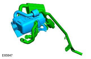
The fuel-fired auxiliary heater is mounted on the coolant supply line to the heater assembly and is located behind the right fender splash guard. Two electrical connectors on the heater assembly are provided to connect it to the vehicle's electrical system.
FFBH includes the following elements:
- Air supply fan
- Combustion chamber housing
- Heat exchanger
- Air intake hose with muffler
- Exhaust pipe with muffler
- Control module
A cross-sectional view of a typical fuel-fired auxiliary heater:
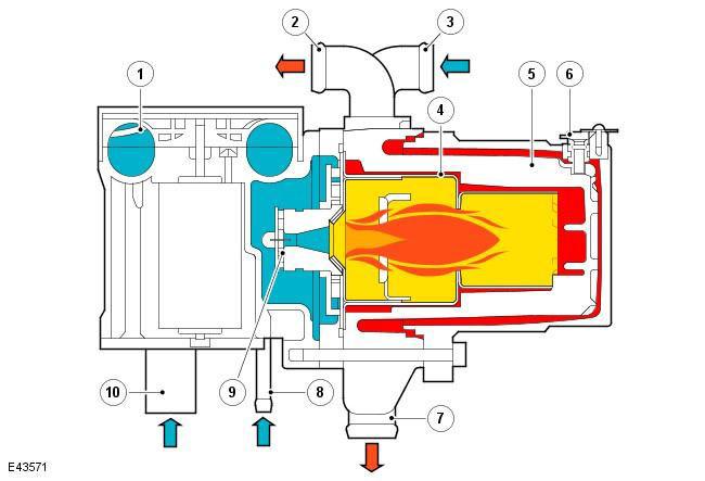
| Pos. | Spare part number | Name |
| 1 | - | Combustion chamber air supply fan |
| 2 | - | Coolant outlet pipe |
| 3 | - | Coolant inlet pipe |
| 4 | - | Refractory insert |
| 5 | - | Heat exchanger |
| 6 | - | Temperature sensor |
| 7 | - | Release |
| 8 | - | Fuel inlet |
| 9 | - | Evaporator |
| 10 | - | Air inlet |
Combustion chamber air supply fan
The combustion air fan regulates the air supply to the FFBH to support combustion of the fuel supplied by the auxiliary fuel pump. It is also used to purge and cool the FFBH.
Combustion chamber housing
The combustion chamber housing contains a fireproof insert, as well as a connector for connecting the outlet pipe and fittings for connecting the hose from the additional coolant pump and the hose to the heater radiator.
The fireproof insert includes a fuel combustion chamber, as well as an evaporator and a glow plug with a flame sensor. Fuel from an additional fuel pump is fed to the diffuser, where it evaporates and then is fed to the combustion chamber, where it mixes with air coming from the combustion chamber air supply fan. The glow plug with a flame sensor provides the initial ignition of the air-fuel mixture, and after the combustion process stabilizes, it controls the flame.
Heat exchanger
The heat exchanger transfers the heat generated in the combustion chamber to the coolant. Two temperature sensors installed in the heat exchanger housing send information about the engine coolant temperature to the control module. The control module uses this information to control the system.
Air intake hose with muffler
The intake air hose has an intake noise muffler installed. The muffler is designed to reduce intake noise.
Exhaust pipe with muffler
The exhaust pipe with a muffler discharges combustion products into the atmosphere at a point located under the right front wheel arch. During operation of the FFBH module, steam may be observed at the outlet, depending on weather conditions.
Control module
The control module controls and monitors the operation of the FFBH. The air flow generated by the combustion chamber fan is used to protect the control module from overheating.
The control module receives constant power from the battery junction box (BJB) and communicates with the ATC module via the medium-speed CAN bus.
Comments on this article