car logo Ford
car logo Volkswagen
car logo BMW
car logo Opel
car logo Audi
car logo Toyota
car logo Peugeot
English Русский
Български
Беларускі
Український
Српски
Hrvatski
Română
Polski
Slovenský
Magyar


Main
Freelander
Discovery
Range Rover
Defender
Contacts
Articles

Additional fuel pump (Freelander 2)

 
  • Main
  • Freelander
  • Freelander 2
  • Electrical equipment
  • Additional climate control
  • Additional fuel pump
 
        1  
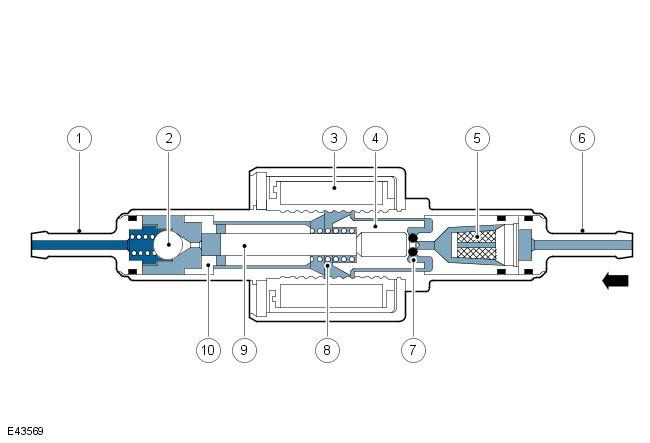
Additional fuel pump


Pos.Spare part numberName
1-Fuel line nipple
2-Check valve
3-Electromagnet winding
4-Plunger
5-Filter element
6-Fuel line nipple
7-Sealing ring
8-Spring
9-Piston
10-Sleeve

The additional fuel pump is mounted on the right side of the fuel tank and regulates the fuel supply to the fuel-fired auxiliary heater. The self-priming pump with electromagnetic drive is controlled by pulse-width modulated signals from the control module in the FFBH. When de-energized, the pump forcibly stops the fuel supply to the auxiliary heater module.

The winding of the additional fuel pump electromagnet is installed on the housing, in which the plunger and piston are located. The piston is located in the bushing, which is acted upon by a spring, resting its other end against the plunger. At the entrance to the housing there is a nipple for connecting the fuel line and a replaceable fuel filter. At the exit from the housing there is a nipple for connecting the fuel line and a check valve.

When the solenoid winding is de-energized, the spring holds the piston and plunger in a position that closes the fuel supply to the pump housing. The sealing ring ensures the plunger is tight and prevents fuel from entering from the filter through the pump. When the winding is energized, the piston and plunger move forward, towards the outlet end of the pump housing, until the piston contacts the bushing. In this case, fuel enters the pump through the inlet connection nipple and the filter. The initial displacement of the piston also closes the transverse holes in the bushing, and isolates the discharge cavity at the outlet end of the pump housing. Further advancement of the piston forces fuel out of the discharge chamber through the check valve into the pipeline leading to the additional fuel-fired heater. After the solenoid winding is de-energized, the spring returns the piston and plunger back to the position that closes the pump. As the piston and plunger are retracted to the closed position, the fuel bypasses the plunger through the annular gaps and transverse holes in the sleeve and again fills the discharge cavity.


This article is available at russian, bulgarian, belarusian, ukrainian, serbian, croatian, romanian, polish, slovak, hungarian
Article review: Roman Mitrofanov


Previous articles
Auxiliary electric heater
Auxiliary fuel heater

Current article
Additional fuel pump

Next articles
Fuel fired auxiliary heater
Additional coolant pump
Remote control elements
Control circuit without remote control
Remote control control circuit
Operating principles of a fuel heater
Removal and installation an electric heater
Removal and installation a fuel heater


Similar articles from Land Rover repair manuals:
• Fuel Pump — Range: 2007->CURRENT Discovery 3 (2004-2009)
• Adjustments — accelerator cable (fuel injection pump lever) Discovery 1 (1989-1998)
• High pressure fuel pump Range Rover 3 (2001-2012)
• Fuel pump — removal and installation Defender 2007+ (2007-2016)

Comments on this article

Артур
03.01.2019
16:03
Как проверить, работает насос или нет? Сколько вольт можно потключять? Играет роль полярность потключения?
answer quote


How much will 43 + 20 =


Freelander 2 
  • General information
  • Using the manual
  • Repair technique
  • Precautionary measures
  • Road test
  • Fault codes
  • Identification codes
  • Jacking and lifting
  • Maintenance - Diesel
  • Maintenance - petrol
  • Chassis
  • Suspension
  • Front suspension
  • Rear suspension
  • Wheels and tires
  • Terrain response
  • Transmission system
  • Cardan shaft
  • Rear drive axle
  • Rear axle shafts
  • Front axle shafts
  • Brake system
  • Parking brake
  • Hydraulic brake
  • Brake booster
  • Anti-lock braking system
  • Exchange rate stability
  • Steering
  • Steering column
  • Power unit
  • Engine device
  • Engine repair
  • Description of the cooling system
  • Cooling system repair
  • Fuel supply
  • Drive units
  • Launch system
  • Ignition system
  • Exhaust toxicity
  • Air filtration
  • Fuel vapor control
  • Electronic control part
  • Automatic gearbox
  • Gearbox cooling
  • Automatic transmission controls
  • Mechanical transmission
  • Transfer case
  • Exhaust system
  • Fuel tank and lines
  • Speed control
  • Electrical equipment
  • Climate control system
  • Climate control
  • Additional climate control
  • Instrument panel
  • Sound signal
  • Information and messages
  • Assistance with parking
  • Battery and alternator
  • Information and entertainment
  • Outdoor Lighting
  • Interior lighting
  • Communication network
  • Wiring harnesses
  • Anti-theft system
  • Multifunctional modules
  • Body and coating
  • Body front panels
  • Lockable body parts
  • Interior trim
  • Rear view mirrors
  • Car seats
  • Glass, frames and mechanisms
  • Instrument panel and console
  • Handles, locks, latches
  • Windshield wipers and washers
  • Sunroof
  • Bumpers
  • Seat belt system
  • Restraint system
  • Body repairs
  • Front end repairs
  • Roof element repairs
  • Side panel repairs
  • Tailgate repairs
  • Subframe and mounts

Freelander 1 
  • General information
  • Using the manual
  • Precautionary measures
  • Technique
  • Specifications
  • Connection tightening torques
  • Maintenance
  • Power unit
  • Diesel engine Td4
  • Petrol engine K1.8
  • Piston group K1.8
  • KV6 petrol engine
  • Piston group KV6
  • Decreased toxicity
  • Motor control EDC
  • Engine management MEMS
  • Motor control Siemens
  • Fuel supply diesel Td4
  • Fuel supply for K1.8 engine
  • Fuel supply of KV6 engine
  • Cooling diesel Td4
  • Engine cooling K1.8
  • Engine cooling KV6
  • Exhaust system Td4
  • Exhaust system K1.8
  • Exhaust system KV6
  • Clutch
  • Mechanical transmission
  • Transfer case
  • Automatic gearbox
  • Chassis
  • Drive shafts
  • Rear axle and final drive
  • Steering
  • Front suspension
  • Rear suspension
  • Brake system
  • Body and coating
  • Passive safety
  • Doors, locks and glass
  • Exterior body parts
  • Interior trim details
  • Seats
  • Roof hatch
  • Roof
  • Body geometry
  • Body parts repair
  • Sealing and corrosion
  • Electrical equipment
  • Heating and ventilation
  • Air conditioning
  • Windshield wipers and washers
  • Starting engine and charging
  • Lighting and headlights
  • Control modules
  • Safety system
  • Window management
  • Entertainment systems
  • Wiring harnesses
  • Governing bodies
  • Devices


LRman.ru © 2013-2026 | Mobile version | Free Lander | Discovery | Range Rover | Defender | Contacts | | Sitemap |
Car repair and service instructions Land Rover: Freelander, Discovery, Range Rover, Defender
We use cookies to make pages load faster and provide a more user-friendly experience 🍪