Contents: Start-up sequence ⇩ Full and partial load ⇩ Disconnection ⇩ Diagnostics ⇩ Remote control operation ⇩ Threshold values for pre-combustion ⇩
When a request to turn on the heating is received at an outside air temperature of 5°C or less, the ATC module transmits an "additional heating" message to the FFBH control module via the medium speed CAN bus. The control module responds by returning an "additional heating" message to the ATC module. The control module then initiates the FFBH start sequence.
When the heating request is removed or if the outside temperature rises to 8°C, the ATC module transmits the message "heater off" to the FFBH control module via the medium-speed CAN bus. The control module responds by returning the message "heater off" to the ATC module. The control module now switches off the FFBH.
If maximum heating is requested, the engine coolant temperature (ECT) becomes the determining factor. In this case, the ATC module changes the CAN bus message from "heater off" to "additional heating" if the engine coolant temperature is 70°C or lower. If the engine coolant temperature rises to 78°C, the ATC module returns the "heater off" message.
The controller will not turn on the flare heater or will interrupt its operation if one of the following conditions exists:
- The control module is blocked due to a fault (see Diagnostics section below).
- The engine does not run or stops for more than 4 seconds. A delay period is provided to detect engine stop.
- A "fuel shut off" message has been received from the CJB on the medium speed CAN bus. For more information, refer to the chapter: Supplemental Restraint System of the Air Bags and Seat Belt Pretensioners (SRS) (501-20B Supplemental Restraint System, Description and Operation).
- A low fuel level message has been received from the CJB on the medium speed CAN bus (see table below). For more information, refer to the chapter: Instrument Cluster (413-01 Instrument Cluster, Description and Operation).
The article was copied from a resource (www.LRman.ru)
The control module controls the operation of the FFBH based on the following fuel levels in the tank:
| Fuel level, liters (US gallons) | Description |
| 7,5 (1,98) | Getting Started |
| 4,5 (1,18) | Termination of work |
| 10,5 (2,77) | Restart |
Start-up sequence
At the beginning of the start-up sequence, the FFBH control module:
- supplies power to the glow plug and flame sensor to preheat the combustion chamber
- starts the combustion chamber air supply fan at low speed
- and supplies power to the auxiliary coolant pump
After approximately 30 seconds, the control module switches on the power supply of the additional fuel pump in the heater start mode. In the combustion chamber, the fuel supplied by the additional fuel pump evaporates, mixes with the air supplied by the fan, and is ignited by the glow plug with a flame sensor. Then the control module gradually increases the performance of the additional fuel pump and the fan supplying air to the combustion chamber. After the combustion process in the combustion chamber has stabilized, the control module switches the glow plug with a flame sensor to the flame sensor mode to monitor the combustion process. From the moment of ignition to stable combustion at full thermal load, approximately 150 seconds pass.
Full and partial load
When the FFBH is operating, the control module selects full load, partial load and idle modes of operation of the fuel-fired auxiliary heater depending on the coolant temperature in the heat exchanger.
The heat output at partial load is 2.8 kW. At full load it increases to 5 kW. The control module reports the amount of fuel consumed to the instrument cluster and the coolant temperature in the FFBH module to the ATC module.
Switching temperature values
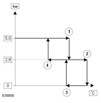
| Switching point | ||
| Element number | Description | Temperature, ºC (ºF) |
| 1 | From full load to partial load | 79ºC (174ºF) |
| 2 | From partial load to idle mode | 90ºC (194ºF) |
| 3 | From idle to partial load | 74ºC (165ºF) |
| 4 | From partial load to full load | 69ºC (156ºF) |
After the start sequence is complete, the control module maintains full load operation until the coolant temperature reaches switch point 1. At this temperature, the control module establishes part load operation by reducing the auxiliary fuel pump and combustion air blower output by approximately half. Part load operation is maintained as long as the coolant temperature remains between switch points 2 and 4. During part load operation, the coolant temperature may rise or fall, depending on the amount of heat required to heat the passenger compartment. If the coolant temperature drops to switch point 4, the control module increases the pump and combustion air blower output, returning to full load operation. If the coolant temperature rises to switch point 2, the control module initiates idle operation.
When the idle mode is activated, the control module immediately turns off the auxiliary fuel pump to stop the combustion process and starts the combustion air fan timer. After a two-minute cool-down, the control module turns off the combustion air fan and then maintains the idle mode as long as the heat exchanger case temperature remains above switching point 3. When the coolant temperature drops to switching point 3, the control module switches the system to part-load mode. From start-up to reaching part-load mode, it takes approximately 90 seconds.
To limit the formation of carbon deposits on the flame sensor glow plug, the control module also enters idle mode if the continuous operation period exceeds 72 minutes (at full load, at part load, or a combination of both). If the coolant still requires additional heating after the cool-down period, the control module restarts the fuel-fired auxiliary heater.
Disconnection
To switch off the FFBH, the control module stops combustion by switching off the auxiliary fuel pump, but leaves the combustion air fan running for a while to cool the fuel-fired auxiliary heater. The cooling period is 100 seconds if the stop is performed from partial load mode and 175 seconds from full load mode.
Diagnostics
The control module monitors the fuel fired auxiliary heater and records faults. Diagnostic trouble codes (DTCs) are stored in the control module's volatile memory and can be retrieved by the Land Rover approved diagnostic system via the medium speed CAN bus.
The control module also has a fault lockout function that stops the system when a fault is detected, preventing it from failing. In fault lockout mode, the control module immediately turns off the auxiliary fuel pump and, after approximately 2 minutes, turns off the combustion air fan and auxiliary coolant pump. Fault lockout occurs in the following cases:
- Violation of the starting procedure and termination of the combustion process: If stable combustion cannot be achieved during startup or the flame disappears after combustion has stabilized, the control module initiates a restart. The unsuccessful startup or flame disappearance is recorded by an event counter in the control module. The event counter increases by one for each unsuccessful startup or flame disappearance and decreases by one for each subsequent successful startup. If the event counter increases to three (for any number of startup cycles), the control module enters the fault lockout mode.
- Overheating of the heat exchanger body: To protect the system from overheating, the control module activates the fault lock mode if the coolant temperature at the heat exchanger outlet exceeds 125°C.
- Battery voltage is out of range: Malfunction lockout will occur if the battery voltage drops below 10.25 and rises above 15.5 V.
Clearing fault information from the control module memory is accomplished using a Land Rover approved diagnostic system or by disconnecting the battery for at least 10 seconds.
Remote control operation
The 868.3 MHz radio signals transmitted by the remote control are received by the DAB/FFBH antenna located in the left rear window. The signals received by the antenna are decoded by the FFBH receiver. A confirmation signal is sent back from the receiver to the remote control to confirm the validity of the on or off request in order to activate the remote control indicator accordingly. The receiver processes the signal it has received and transmits the appropriate signals to the FFBH control module via a special bus.
NOTE: The confirmation signal only confirms that the data exchange between the remote and receiver was successful and does not confirm that FFBH has been enabled.
When the FFBH is activated by the remote control, the control module allows the FFBH to operate for 30 minutes or until a request to turn it off is received from the remote control or the CJB. During the 30 minute period, the FFBH can operate in full load, part load or idle mode, depending on the coolant temperature in the heat exchanger.
Threshold values for pre-combustion
The FFBH unit will be activated remotely when the following conditions are met:
- Pre-burn battery voltage test: ≥11.5V (FFBH terminal voltage)
- Pre-combustion coolant temperature check: ≤15°C (FFBH internal measurement)
- Pre-combustion fuel level check: ≥7.5 l (value stored in FFBH with ignition off)
The fuel level value stored in the FFBH unit is updated only when the engine is running. When starting the FFBH by remote control with the engine off, the fuel level value used in the FFBH calculations will be the value stored when the ignition was last turned off. Therefore, it is possible that the FFBH will not be able to operate under remote control if the engine was stopped with a low fuel level; if the fuel tank is then refilled, the fuel level stored in the FFBH will still read low unless the engine has been started since refilling.
If the FFBH does not activate due to low battery voltage or low fuel level, its control module transmits a message via the medium and high speed CAN buses, via the CJB to the instrument cluster message centre which will display one of the following messages when the ignition is on:
- AUXILIARY HEATER UNAVAILABLE LOW FUEL
- AUXILIARY HEATER UNAVAILABLE LOW BATTERY
If both messages (low fuel and low battery) are valid, the instrument cluster message center will alternate between displaying the two messages.
Transitions from the" Park Heat "mode of the remote control to the "Supplementary Heat" mode of the ATC
NOTE: FFBH can still be activated by the ATC module as described above
If FFBH was working in remote mode ("park heat") and the vehicle is started while FFBH is still active, a transition to ATC 'supplementary heat' control mode will be performed if ATC requests it.
If ATC then sends a message to the FFBH to turn off, the FFBH will remain active until 30 minutes have passed from the original 'park heat' request via the remote control. After the remainder of the 30 minutes, the FFBH will turn off.
Switching temperature values
With remote start, the FFBH uses a different set of switching temperature values for the normal 'supplemental heat' mode. The reason is that the remote start function can start the FFBH when the engine is switched off - so different threshold values are required to optimise the heating of the engine coolant.
Switching temperature values:

| Switching point | ||
| Item No | Name | Temperature, ºC (ºF) |
| 1 | From full load to partial load | 80ºC (176ºF) |
| 2 | From partial load to idle mode | 90ºC (194ºF) |
| 3 | From idle to partial load | 50ºC (122ºF) |
| 4 | From partial load to full load | 70ºC (158ºF) |
Comments on this article