Fuel system diagram
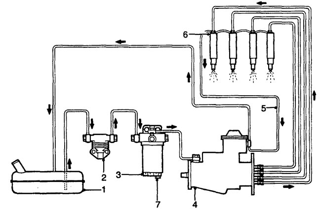
1 - fuel tank, 2 - mechanical booster pump, 3 - fuel filter, 4 - Bosch VE fuel injection pump, 5 - drain, 6 - injectors, 7 - filter drain plug.
Location of system components
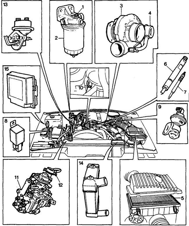
1 - Fuel filter drain screw, 2 - Fuel filter, 3 - Turbocharger, 4 - Bypass valve, 5 - Air filter, 6 - Injector, 7 - Glow plug, 8 - Glow plug relay, 9 - EGR valve and valve lift sensor, 10 - Coolant temperature sensor (recirculation systems), 11 - high-pressure fuel pump, 12 - high-pressure fuel pump lever position sensor, 13 - booster pump, 14 - charge air cooler, 15 - recirculation system control unit.
(Data taken from the website: www.LRman.ru)
Comments on this article