Location of components of the electronic control system
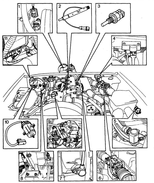
1 - vehicle speed sensor, 2 - needle lift sensor (4th injector), 3 - coolant temperature sensor, 4 - boost pressure sensor, 5 - electropneumatic modulator, 6 - air flow sensor, 7 - speed sensor, 8 - brake/clutch switches, 9 - fuel injection pump, 10 - fuel injection pump lever position sensor (electronic pedal), 11 - engine control unit.
Electronically controlled fuel system diagram
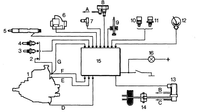
1 - fuel injection pump, 2 - fuel temperature sensor, 3 - air temperature sensor, 4 - coolant temperature sensor, 5 - needle lift sensor (4th injector), 6 - air flow sensor, 7 - speed sensor, 8 - boost pressure sensor, 9 - vehicle speed sensor, 10 - clutch pedal switch, 11 - brake pedal switch, 12 - fuel injection pump lever position sensor, 13 - electro-pneumatic modulator, 14 - exhaust gas recirculation valve, 15 - engine control unit, 16 - diagnostic unit lamp, A - to turbocharger, B - to air receiver, C - to brake booster tee, D - injection advance change traction relay, E - fuel cut-off valve, F - supply wire to metering unit drive, G - control spacer.
(The source of the article is located on the website: «LRman.ru»)
Comments on this article