Contents: Dismantling ⇩ Installation ⇩
Dismantling
1. Raise the vehicle on a four-post lift.
2. Raise one wheel of each axle, if necessary, in order to rotate them to gain access to the driveshaft mounts.
CAUTION: When working with cardan shafts:
- The cardan shaft and viscous coupling must be removed only as an assembly. Dismantling the viscous couplings may result in their damage.
- Do not remove the viscous coupling support bearing mounting bolts from the body without first removing the driveshafts from the differential and transfer case. The weight of the center section will stretch the viscous coupling in different directions, which will cause irreparable damage.
- Do not allow the viscous coupling to bend. This will cause the internal roller bearings to break, the clearance to increase, and the viscous coupling to fail.
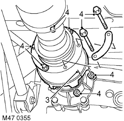
3. To facilitate subsequent assembly, apply marks of relative positions to the flanges of the cardan shaft.
4. Remove the 6 bolts and nuts with tightening washers that secure the viscous coupling to the transfer case flange.
5. Pull the viscous coupling housing and move it away from the transfer case flange. If necessary, place a clamp on the viscous coupling housing and move the coupling away from the transfer case flange, resting the lever against the clamp. Support the front of the propeller shaft.
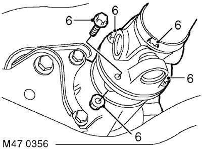
6. Unscrew the 4 nuts and bolts securing the propeller shaft to the rear axle flange, move the propeller shaft away from the rear axle flange and support it.
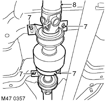
7. Unscrew the 4 bolts securing the viscous coupling support bearings.
CAUTION: It is necessary that the weight of the coupling and the propeller shaft be supported by supports.
8. With the help of a partner, remove the propeller shaft assembly.
Installation
1. Clean the propeller shaft flanges and mating surfaces.
2. With the help of a partner, install the driveshaft assembly into place, supporting its front and rear parts.
3. Install the viscous coupling support bearing mounting bolts, but do not tighten them at this stage.
4. Install the propeller shaft on the rear axle and align the relative position marks.
5. Install the bolts and nuts securing the rear flange of the propeller shaft and tighten them to a torque of 65 Nm.
6. Install the cardan shaft on the transfer case flange and align the relative position marks.
7. Install the bolts and nuts securing the front flange of the propeller shaft to the transfer case and tighten them to a torque of 40 Nm.
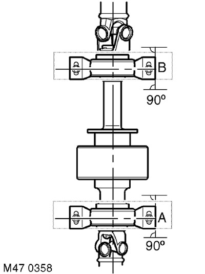
8. Position the support bearings at 90 degrees to the axle as shown at points 'A' and 'B', tighten the rear bearing bolts and then the front bearing bolts. Tightening torque 28 Nm.
9. Lower the wheels.
10. Lower the vehicle.
Comments on this article