Contents: Removal ⇩ Installation ⇩
NOTE: Rear side member section from rear side member service panel. Section is approximately 410mm long and is serviced together with the rear side member lower extension.
NOTE: To access the rear side member section, the spare tire well must be removed.
Removal
1. In combination with the rear side member section, the following is replaced:
- Rear bumper trim
- Rear bumper fittings
- Tail panel
- Rear bumper mount
- Inner side of the rear panel assembly
- Rear side member closing panel.
- Spare wheel niche
- Fuel tank
- Rear subframe and suspension assembly
2. For additional information regarding this repair procedure, refer to: For additional information, refer to: Body and Frame (501-26 Body Repairs - Special Vehicle Information and Tolerance Checks, Description and Operation) / Standard Service Station Techniques (100-00 General Information, Description and Operation).
3. Remove the rear side member end panel. For more information, refer to the chapter: Rear Side Member End Panel (501-30 Rear Sheet Metal Repairs, Removal and Installation).
4. Remove the rear subframe/suspension assembly. For more information, refer to the chapter: Rear Subframe (502-00 Uni-Body, Subframe and Mounting System, Removal and Installation).
5. Remove the fuel tank. For additional information, refer to the chapter: Fuel Tank (310-01A Fuel Tank and Fuel Lines - 3.2L NA - I6, Removal and Installation).
6. Mill out the weld spots.
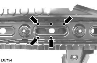
7. Cut off the old panel at the point shown.
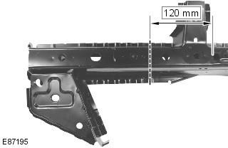
8. Separate the connections and remove the old panel.
Installation
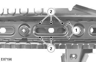
1. Remove the amplifier section from the old panel.
- 1. Cut the reinforcement at the point shown, do not cut the side member.
- 2. Mill 5 spot welds.
- 3. Separate and remove the rest of the amplifier.
NOTE: The old side member and the new reinforcement section cuts must be spaced at least 50 mm apart.
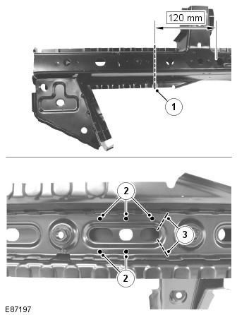
2. Remove the rear side member section from the service panel:
- 1. Cut the side member at the point shown, do not cut the reinforcement.
- 2. Mill 5 spot welds.
- 3. Cut the amplifier at the point shown.
- 4. Separate and remove the side member section.
NOTE: The old side member and the new reinforcement section cuts must be spaced at least 50 mm apart.
3. Prepare the connecting surfaces of the old and new panels.
4. Drill holes in the new panel for MIG welding.
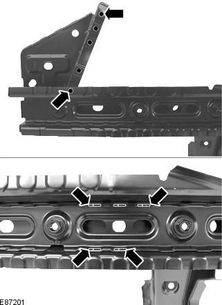
5. Apply the new panel and fix it in place. Check the alignment, if correct, proceed to the next step, if not, correct and check again before proceeding to the next step.
6. Fix the panels and tack the butt joints.
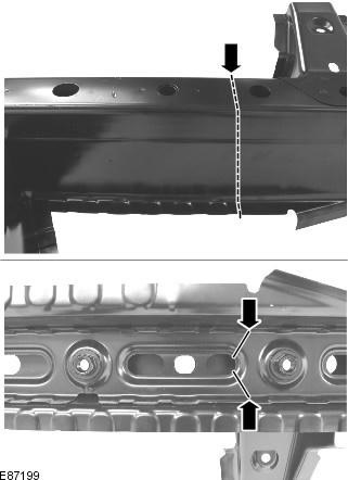
7. Clean the tack welds.
8. Perform butt welding using MIG technology.
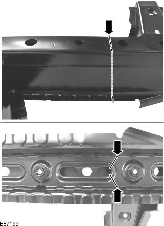
9. MIG welding.
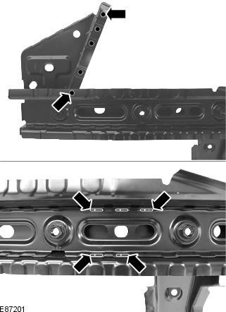
10. Clean all welded joints.
11. To install the relevant panels and mechanical components, perform the removal procedure in reverse order.
Comments on this article