CAUTION: The same electrical connector housing can contain pins of different sizes and types.
It is necessary to determine:
- Cross-section of the wire in the faulty wiring harness
- The area with the electrical connector from which the damaged wiring harness must be removed
- Contact type
Using the recommended diagnostic tool greatly facilitates and speeds up the identification of electrical connectors and faulty contacts.
You can also refer to the wiring diagrams of the car (available from dealers) for identifying wire harnesses and electrical connectors.
In the mapping table, you can determine the size of the wire in the wire harness for a suitable bundle with insulation color termination. In addition, here you can determine the correct length of insulation trim on the wiring harness.
Mapping table
| CABLE RANGE | SPHERE | STRIPING LENGTH |
| 0.35 to 1.50 mm² | RED | 6.00 to 7.00 mm |
| 1.00 to 2.50 mm² | BLUE | 6.00 to 7.00 mm |
| 4.00 to 6.00 mm² | YELLOW | 9.00 to 9.50 mm |
Removing contacts from electrical connectors
It should be noted that some electrical connectors are equipped with latches that prevent the pins from being pulled out of the connector. The following illustrations show examples of such connectors. Before removing the contact from the electrical connector, you must disconnect the retainer. Some clips require a special lug to release (available in the kit). Most retainers can be released with a suitable small screwdriver.
Some types of electrical connectors have internal or external seals to prevent moisture ingress. It is not normally necessary to remove these seals, but check for them when connecting the electrical connectors.
The illustrations show examples for each ferrule used for various types of electrical connectors. There are a large number of different types of electrical connectors, so only one example is given for each tip. To select a ferrule for electrical connectors not shown, the technician must use experience and common sense. Care must be taken to prevent further damage when removing the pins from the electrical connector.
NOTE: Examples of tips for extracting contacts and detaching retainers.
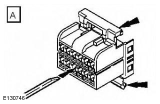
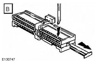
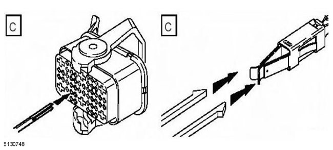
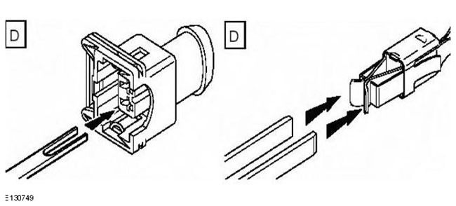
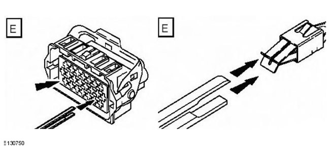
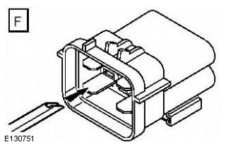
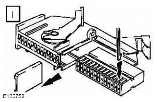
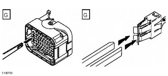
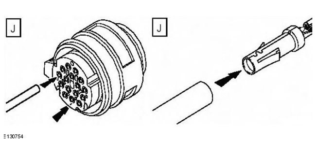
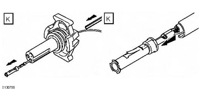
NOTE: The diagram shows electrical connector types, pins/sockets, pin extraction lug, and retainer release lug.
| Type of contact in the electrical connector | Pin or socket | Extraction tip | Tip for detaching the retainer |
| Mulitlock 040 Series | D | A | |
| Mulitlock 040 series | B | A | |
| Mulitlock 070 series | B | B | |
| Mulitlock 040 series | D | B | |
| Series Econoseal III 070 | D | B | |
| Series Econoseal III 070 | B | B | |
| Series Econoseal III 070 | B | B | |
| Econoseal III J2 | D | B | |
| Econoseal III 250 series | B | F | |
| Econoseal III 250 series | D | B | |
| Econoseal III 250 series | B | F | |
| Econoseal III 250 series | D | B | |
| Microtimer II 1.5 mm | D | C | |
| Microtimer II 1.5 mm | B | C | |
| Standard Power Timer 4.8 flat | D | G | |
| Standard Power Timer 5.8 Flat | B | D | |
| Standard Power Timer 5.8 Flat | B | D | |
| Standard Power Timer 2.8 flat | D | D | |
| Standard Power Timer 4.8 flat | D | G | |
| Standard Power Timer 5.8 Flat | B | D | |
| Ford 2.8 flat | D | E | H |
| Mulitlock 070 Series | D | B | |
| Mulitlock 070 Series | B | B | |
| Junior power timer 2.8 flat | D | D | |
| Sumitomo TS90 connector | B | B | H |
| Modu IV gold plated | D | B | |
| Mulitlock series 040 gold plated | D | A | |
| Micro qualock | D | I | |
| EECV | D | B | |
| EECV | D | B | |
| Kostal series diam. 1.50 | D | J | |
| AMP 6.3 flat | D | B | |
| Junior power timer 2.8 flat | D | D | |
| Series 2.8 | D | B | I |
| Sumitomo TS90 connector | D | B | H |
| Ducon 0.60 gold plated | D | K | |
| AMP 6.3 flat | D | D | |
| Econoseal III 250 series | B | F |
Comments on this article