Do not use crimpers, wire strippers, butt connectors, heat shrink sleeves or pre-terminated wire harnesses other than those included in the Jaguar Wiring Harness Repair Kit. Each part is designed for use only with other parts in the Wiring Harness Repair Kit.
If the repair procedure specifies the use of adhesive heat shrink sleeve, heat the sleeve to the melting point of the adhesive to ensure a tight seal. Do not overheat the adhesive heat shrink sleeve to avoid damaging the wire harness insulation.
No more than five repair splices should be made in a wire harness for any electrical connector; if more than five faults are found in one electrical connector, a new wiring harness must be installed.
Using an extractor and the correct tip, remove the faulty contact from the electrical connector. Make sure the retainer is released before removing the contact.
CAUTION:: Some contacts in the electrical connectors are gold plated or gold-plated. If they fail, they should be replaced with a gold plated wire harness and termination from the wire harness repair kit. It is difficult to determine whether a jack is gold plated, but it is easier to visually identify the contacts on the plug, so be sure to check both the jack and the plug for gold plated contacts. Never mix gold plated and tin plated contacts, as this will cause premature failure of the electrical connector.
NOTE: Do not use a wire with a smaller diameter than the original in the harness.
Select the correct size and type of wire harness and butt connector from the wire harness repair kit.
Using the wire cutters on the wire stripper, cut the wire harness and harness cable to the desired length.
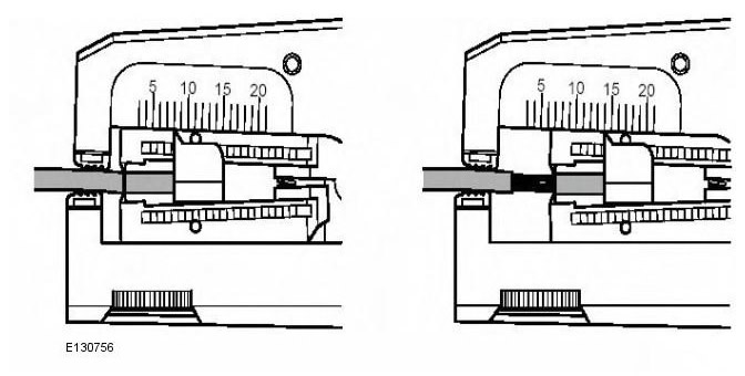
NOTE: See illustration: Stripping insulation
Find the correct insulation strip length on the pre-terminated wire harness in the comparison chart and set the correct length on the adjustable stopper. Clamp the pre-terminated wire harness in the wire stripper and remove the insulation.
Place the cable identification sleeves on the wire harness so that the main color of the cable is at the terminal.
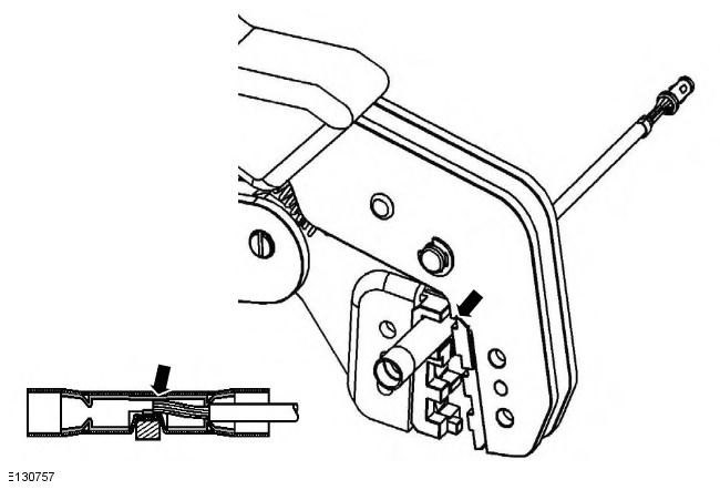
In the next step, do not over tighten. Place the selected butt connector into the crimping tool, making sure the holes and colors of the butt connector match. Make sure the recess on the butt connector is positioned over the guide of the lower clamp. Partially squeeze the handles until the butt connector is firmly seated in the hole. This will ensure that the butt connector will not move when the pre-terminated wire harness is installed into it.
NOTE: See illustration: Correct splice location
Insert the pre-terminated wire harness into the butt connector, making sure the wire is against the stop. Squeeze the handles tightly, crimping the wire into the butt connector. When the handles are fully closed, the butt connector will release from the tool as they open. If the handles are not fully closed, the clamps will hold the butt connector and it will not be removed from the tool until the wire is fully crimped (the handles are fully closed).
Ensure that the harness cable is cut correctly and the correct amount of insulation is removed. If multiple splice points are required, butt connectors should not be crimped onto the harness at the same distance from the electrical connector. Splice points should be staggered to prevent multiple splice points from being located in the same area of the harness.
It is recommended to cover the splice with heat shrink sleeve. This is not a requirement except for electrical connectors with seals. The small diameter sleeve is used for red and blue wire harnesses with terminations, and the large diameter sleeve is used for yellow. It is recommended to place heat shrink sleeve over the finished joint, however, in some cases the sleeve will not fit over the contact. Check and, if necessary, install the correct size sleeve on the harness cable or on the wire harness with terminations before crimping the splice to the wire harness.
Place the wire harness cable into the butt joint so that the hole is positioned above the guide. Make sure the wire harness is pressed against the stop in the butt joint, then crimp the butt connector onto the wire harness.
Gently pull the wire harness on both sides of the splice to check for a secure connection.
WARNING: Do not use an open flame in areas where there is spilled fuel or oil. Clean the area of any remaining oil or fuel and allow any spilled fuel to evaporate.
When using a heat source, ensure it is localized and will not damage surrounding materials.
If the repair procedure specifies the use of adhesive heat shrink sleeve, heat the sleeve to the melting point of the adhesive to ensure a tight seal. Do not overheat the adhesive heat shrink sleeve to avoid damaging the wire harness insulation.
Using a suitable heat source, heat shrink the sleeve at the splice location.
(The full version is available on the website LRman.ru)
If additional splice harnesses are to be installed on the same electrical connector, be sure to cut the wire at a different distance from the previous splice. This will ensure that the splice points on the harness are spaced out (if possible) and prevent multiple splices from occurring in one location.
Once splicing is complete, install the contacts into the electrical connector. Ensure that the contacts are oriented correctly.
Install the harness cover and secure with adhesive tape. Do not cover the harness all the way to the electrical connector, as the contacts should have some movement and not be permanently sealed in the connector or harness. Make sure the identification sleeves are visible at the electrical connector of the harness.
Stripping insulation
Correct location of the splice
Comments on this article