Eight wiring harnesses were modified to accommodate the Stop/Start system.
Automatic Stop/Start system control diagram:
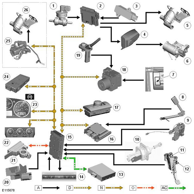
NOTE: A = Wired connection; D = High Speed CAN Bus; N = Medium Speed CAN Bus; O = LIN Bus; AC = diagnostic channel.
| Pos. | Spare part number | Name |
| 1 | - | Brake booster vacuum sensor |
| 2 | - | Engine Control Module |
| 3 | - | Neutral gear sensor |
| 4 | - | Battery Distribution Box |
| 5 | - | Additional coolant pump* |
| 6 | - | Starter |
| 7 | - | Descent control switch |
| 8 | - | Driver's seat belt switch |
| 9 | - | Driver's door open warning switch |
| 10 | - | Linear Clutch Switch |
| 11 | - | Upper Clutch Pedal Switch |
| 12 | - | Lower clutch pedal switch |
| 13 | - | Voltage Quality Control Module |
| 14 | - | Stop/Start switch and LED status indicator |
| 15 | - | Central distribution box |
| 16 | - | Passive safety system control unit |
| 17 | - | Terrain Response Control Unit |
| 18 | - | ABS (anti-lock braking system) unit |
| 19 | - | Wheel speed sensor |
| 20 | - | Hood open warning switch |
| 21 | - | Battery monitoring system module |
| 22 | - | Automatic temperature control unit |
| 23 | - | Instrument panel |
| 24 | - | Trailer block |
| 25 | - | Fuel fired auxiliary heater (if equipped) |
| 26 | - | Additional coolant pump** |
* Vehicles without additional fuel-fired heater.
** Vehicles with additional fuel-fired heater.
Comments on this article