Contents: Voltage quality control unit ⇩ Battery monitoring system ⇩ Neutral gear sensor ⇩ Linear Clutch Sensor ⇩ Brake booster vacuum sensor ⇩ Auxiliary coolant pump ⇩ Remote control ⇩ Starting the engine after it has…⇩ Towing a trailer ⇩ Microclimate control system ⇩ Hood open warning switch ⇩ System failure ⇩
The new and upgraded components described in this section ensure virtually trouble-free operation of all vehicle systems during the Stop/Start cycle.
Voltage quality control unit
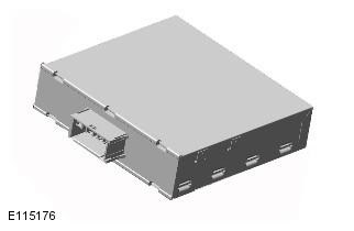
During the Stop/Start cycle, the VQM (Voltage Quality Module) supports the vehicle's electrical systems by supplying auxiliary voltage to electronic components during engine restarts. This allows critical vehicle systems to continue to operate smoothly during sudden, sharp increases in battery current consumption.
The car starter uses 2 kW of electricity and can draw several hundred amps of current from the battery during cranking. The sudden increase in current draw causes a momentary drop in voltage throughout the car's circuits. Many car electronic systems are designed to operate at a nominal 12 volts, so a sudden drop in battery voltage without a VQM installed will temporarily interrupt the following functions:
- audio system
- cell phone
- navigation system
- information panel
When the engine is running, the ECM signal activates the VQM relay to bypass the converter and voltage control returns to the normal charging system. The VQM boosts the voltage for one second, although in many cases it can do this for up to 5 seconds.
VQM is a DC-DC (Direct Current) converter that converts a variable 6VDC input voltage to a stable 12±0.5VDC output voltage.
Rated at 180W, it can supply up to 15 amps at 12V. The VQM can handle instantaneous surges of up to 300W, which is enough to keep the vehicle's systems powered while the engine is cranking.
VQM faults are transmitted via the diagnostic channel to the CJB where they are recorded; fault codes can be diagnosed using Land Rover recommended diagnostic equipment.
Battery monitoring system
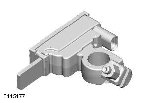
The BMS (Battery Monitoring System) module is mounted on the negative terminal of the battery and is part of the negative battery cable.
Battery condition is a fundamental factor in the proper operation of the Stop/Start system. Battery condition is calculated by the BMS module and will initiate a Stop Interlock or Start Actuator cycle in the Stop/Start cycle if the battery does not meet requirements. For more information, see Stop Interlocks, Start Actuators, and Start Interlocks below.
Battery status information is transmitted from the BMS module via the LIN bus (LIN communication protocol) to the CJB, which has a two-way data link with the BMS module. The control logic for inhibiting engine shutdown and initiating early restart during the Start/Stop cycle is located in the CJB. The CJB also acts as a gateway, transmitting this information to the ECM via the high-speed CAN bus.
Battery status information is also transmitted from the CJB via the medium speed CAN bus to the instrument cluster. The instrument cluster displays battery charge warning messages indicating faults in the alternator or battery monitoring system.
The BMS module continuously calculates the state of the electrical system based on the following data:
- battery aging
- battery charge level
- battery power requirement
If any of these parameters show an insufficient value, the ECM suspends the Stop/Start function until the available battery charge increases. These parameters are listed below:
Aging of the battery
Even though your vehicle has a high-performance battery made with AGM (Absorbent Glass Mat) technology, the battery's ability to hold a charge will still degrade, albeit at a much slower rate than conventional batteries. This aging is reflected in the amount of charge the battery can hold before it needs to be replaced.
The battery monitoring system calculates the battery condition based on monitoring a number of parameters:
- air temperature
- charge and discharge procedures
- voltage
- internal resistance
The latest battery parameter is stored in a dedicated section of the BMS memory to ensure the most accurate prediction of the battery condition.
State of charge
The BMS analyzes the amount of charge consumed or replenished to determine the current battery charge.
Nutritional needs
During the Stop/Start cycle, when the demands of the vehicle systems are high, for example when the following are running simultaneously:
- headlights
- microclimate control system
- audio system
The battery drains faster due to high current consumption.
In this case, the BMS calculates various factors to determine how long the battery can supply power at the current consumption level. This calculation is used by the CJB to determine whether one of the following actions is required in the Stop/Start cycle:
- block engine shutdown
- activate engine restart
To communicate this data to the CJB, the BMS module calculates a number of battery parameters, including:
- state of charge
- battery surface temperature to calculate internal temperature
- internal resistance
- voltage
- electric current flowing into and out of a battery
The battery monitoring system calculates these variables from programmed battery behavior patterns to determine how long the current can be maintained.
Operating modes of the battery monitoring system
The battery monitoring system has three main modes:
- Active mode: During normal vehicle operation, battery data is downloaded and processed every second.
- Standby mode: When the ignition is off, battery data is downloaded every two seconds and calculated every hour to reduce current leakage in the inactive state.
- Transport mode: battery monitoring intervals are minimal.
Replacing the battery
If a new battery is installed in the vehicle, the BMS (battery monitoring system) unit requires recalibration to take into account the increased battery capacity; this is done using Land Rover approved diagnostic equipment. If the diagnostic system is not available, the BMS will automatically recalibrate, but this may take up to 48 hours depending on vehicle usage. The Stop/Start system will not function correctly until the BMS has been recalibrated.
If the BMS module is replaced, its calibration is performed automatically.
CAUTION: To avoid damage/malfunction of the BMS module, be sure to use a suitable ground point on the vehicle body and not the negative battery terminal.
For additional information, refer to the chapter: Battery (414-01 Battery, Battery Mounting and Cables, Diagnostics and Tests).
Neutral gear sensor
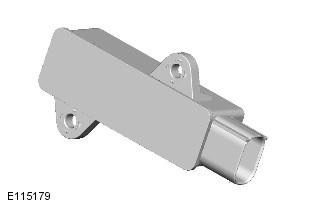
The PLCD sensor (permanent magnetic linear displacement sensor) is located on the outer surface of the transmission housing and is hardwired to the ECM. The sensor is designed to detect neutral gear engagement within a calibrated window.
No calibration is required when replacing the neutral sensor, however it is monitored and a DTC will be stored if a fault occurs. Fault codes can be diagnosed using Land Rover approved diagnostic equipment.
Linear Clutch Sensor
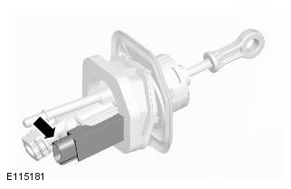
To ensure timely engine restart in the Stop/Start cycle under variable city driving conditions, the engine is started within approximately 800 milliseconds. This is achieved by a linear clutch sensor that initiates engine restart when the clutch pedal is at the initial downward movement point. Therefore, while the clutch pedal is moving downward, the engine restart procedure is already underway.
The linear clutch sensor is a PLCD type sensor (permanent magnet linear contactless sensor) and is located on the clutch master cylinder and is connected by a wire connection to the CJB. The sensor continuously transmits a signal to the CJB about the position of the clutch pedal; this information is transmitted to the ECM via the high-speed CAN bus. The home point signal is used to allow automatic engine restart if all other required conditions are met.
The linear clutch sensor also provides a bottom-of-travel signal when the clutch pedal is near its bottom-of-travel position. This signal is used when the engine stalls and permission to start is required. This is a unique feature that automatically restarts the engine when all other necessary conditions are met. For more information, see the section "Restarting a Stalled Engine" below.
The linear clutch sensor receives information about the position of the clutch pedal from a magnet in the clutch master cylinder. Therefore, if the master cylinder is replaced, it must be selected and installed correctly.
The two existing clutch pedal position sensors, located on the clutch pedal and transmitting signals to various vehicle systems, are also used by the Stop/Start system to check the reliability of the signals.
If the linear clutch sensor fails, a DTC will be stored in the CJB.
NOTE: The Stop/Start system will not operate properly if the driver keeps his/her foot on the clutch pedal while driving.
Brake booster vacuum sensor
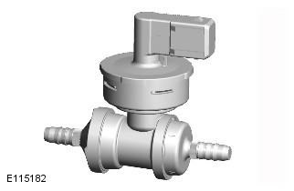
To ensure the constant operability of the brake system, vehicles with the Stop/Start system are equipped with a brake booster vacuum sensor that monitors the presence of vacuum in the brake servo. The vacuum sensor is installed in a vacuum tube and is connected by wires to the ECM. If the vacuum in the brake system during the Stop/Start cycle falls below a preset threshold, the ECM sends one of the following signals:
- Restart the engine and maintain a constant vacuum.
- Block engine shutdown if vacuum level is insufficient.
An example of vacuum loss is when the driver repeatedly presses the brake pedal while the engine is off in a Stop/Start cycle. This action initiates a restart of the engine if the vacuum level drops below a preset threshold.
If the brake booster vacuum sensor fails, a DTC will be stored in the CJB.
Auxiliary coolant pump
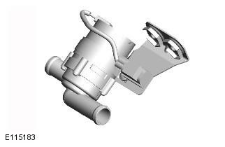
During the Stop/Start cycle, when the engine is switched off and therefore the coolant pump is not operating, it is impossible to maintain the set cabin temperature for a long time, especially at low ambient temperatures. To solve this problem, an auxiliary electric coolant pump has been added to the cooling system, which ensures the passage of liquid through the interior heater radiator. This auxiliary circulation allows the set cabin temperature to be maintained for a longer period of time and prevents premature restart of the engine.
Depending on the vehicle class, the auxiliary coolant pump may be:
- Connected by wires to the ECM.
- Or if the vehicle is equipped with a FFBH (fuel fired booster heater), the FFBH coolant pump may be used, activated via the FFBH.
The functions of both types of auxiliary coolant pumps are the same as far as the Stop/Start system is concerned.
To muffle the sound of the auxiliary pump turning on, it is activated simultaneously with the engine turning off.
Remote control
A new remote control removal system has been developed for driver convenience. This allows the driver to instantly remove the remote control from the start control unit when the engine is switched off in the Stop/Start cycle.
If the Stop/Start system is disengaged, the standard remote control removal procedure is followed: pressing the ignition on/off button before removing the remote control.
(The source of the article is located on the website www.LRman.ru)
Starting the engine after it has stalled/shut off
If the engine stalls, the Stop/Start system enters a unique restart mode. This feature automatically attempts to restart the engine when the driver fully depresses the clutch pedal - a natural driver response to a stalled engine.
When the clutch pedal position sensor detects the threshold of the bottom of the pedal stroke (see "Linear Clutch Sensor"), the starter is activated to start the engine. The instrument panel warning lights normally associated with engine shutdown (e.g. ignition and low oil pressure lights) are then blocked and do not come on. The Eco indicator remains on.
The "stalled engine restart" event is the only condition in which the Stop/Start system allows the engine to start while the transmission is in gear; hence the requirement to fully depress the clutch pedal. If the restart fails and the engine does not start, the message "engage neutral" is displayed on the information panel to retry the restart.
If the stalled engine cannot be restarted after this request, this restart mode will time out and will be switched off. At the same time, the "Eco" icon on the instrument panel will go out and the warning lights that normally indicate a stalled engine will come on. This will require the driver to perform the standard engine restart procedure.
Although engine restart is a function of the automatic Stop/Start system, it can be activated independently of the Stop/Start settings. For example:
- If the automatic Stop/Start system has been switched off by the driver, the restart function will still be active.
- The restart function is activated at ambient temperatures down to -2°C, while the operating temperature threshold of the Stop/Start system is above 4°C.
- Unlike the automatic Stop/Start system, the restart function will remain operational when towing; see the "Towing a Trailer" section.
NOTE: Since the required criteria are not met when the vehicle is driven, the restart function will not work. For example, if the vehicle stalls while leaving the garage or driveway, the engine will need to be restarted in the normal manner.
Towing a trailer
The Stop/Start system is automatically deactivated if the CJB detects trailer lighting via signals from the trailer module; this information is then transmitted to the ECM. The system is unable to determine when the trailer power cable is connected to the vehicle's connector, so it uses the operation of the trailer lighting as an indicator.
The trailer towing system overrides the automatic Stop/Start system because it is possible that the trailer's power consumption could interfere with the battery monitoring system. In particular, the trailer battery could create a reverse current when starting the engine. This could have the following consequences:
- mislead the battery monitoring system into detecting an unrealistically low current when the engine is started
- blow up the trailer module fuse
Microclimate control system
NOTE: The "ECON" button has been renamed "A/C" to avoid confusion with the Stop/Start "Eco" button.
A number of corrections were also made to the logic and operation of the microclimate control system in the Stop/Start cycle:
- maintaining the comfort of the driver and passengers
- preventing windshield fogging
- saving battery power
This is achieved by means of monitoring the ATC (automatic climate control) unit and, if necessary, by changing various climate control functions in the Stop/Start cycle.
In some cases, ATC can inhibit engine shutdown or initiate a restart during a Stop/Start cycle. This is achieved by communication between the ATC module and the CJB over the medium speed CAN bus. The following describes the various inhibit functions in ATC during a Stop/Start cycle:
Coolant temperature
The ATC module inhibits engine shutdown or initiates an engine restart during the Stop/Start cycle if the coolant temperature drops below a calculated threshold to ensure that the set cabin temperature is maintained.
Windshield fogging removal
The modification of the climate control system determines the changes made to the software control. For example, the basic version of the climate control system is not equipped with a humidity sensor, which initiates the windshield blowing in high-level systems. Therefore, the calculation of the windshield defogging is carried out based on signals from the rain sensor and the ambient air temperature sensor. Considering the possibility of the windshield fogging during rain and at low ambient temperatures, ATC assumes the need for defogging and starts the engine in the Stop/Start cycle.
The temperature of the evaporator - the main cause of windshield fogging - is also monitored, and the high-level climate control system periodically cools the evaporator as needed to reduce fogging during the Stop/Start cycle. The system operates the windshield defogging flap, and if there is high humidity in the evaporator, the flap remains closed for a few seconds after the engine is restarted, until the vapors are cleared.
If the driver selects "programmed defrost" or "windshield heater" mode, it is assumed that a quick wipe of the windshield is required. In this case, ATC will perform one of the following actions via the CJB: inhibit engine shutdown or initiate engine start.
Heater fan speed
When the engine is off, ATC monitors the interior temperature and maintains the fan speed at the level required to maintain heat in the interior heater core for as long as possible. If the driver turns on a higher fan speed and heat cannot be maintained in the heater core, the engine will be restarted.
Heated rear window and heated seats
If the heated rear window or heated seats are on, or if they are activated when the engine is switched off, the power supply to the corresponding system will be cut off until the engine is restarted. An indicator on the corresponding switch will light to indicate that the system is active even if it is not receiving power. This function is used to conserve battery power.
Fuel fired heater
FFBH (fuel fired booster heater) and Stop/Start system cannot operate simultaneously because low ambient temperature is a factor in both systems.
Hood open warning switch
WARNING: To avoid injury during vehicle repairs, be sure to turn off the automatic Stop system./Start" by pressing the"ECO" button"; make sure that the message "Stop/Start system off" is displayed on the information panel and the ECO indicator in the switch is off.
The bonnet open warning switch, hardwired to the CJB, has two functions:
- Serves as an engine shut-off interlock, allowing the engine to run with the hood latch open.
- Disables the Stop/Start system when the engine is stopped; as a result, a stalled engine condition occurs. The engine can be restarted by pressing the ignition button. In this case, restarting the stalled engine does not occur; see the section "Restarting a stalled engine".
After closing the bonnet, the automatic Stop/Start system is activated by manually restarting the engine.
System failure
The Stop/Start system is automatically activated each time the ignition is turned on; the system is operational when the indicator in the Eco switch comes on. If the indicator does not come on, the system is faulty or unavailable. The message "ECO STOP/START FAULT" (Starting the Stop/Start system using the ECO button does not work) appears on the information panel only if the driver tries to activate the system by pressing the Eco button.
Due to the complexity of the Stop/Start system, as many other modules and vehicle communication networks are involved in the operation of this function. When examining the Stop/Start system for faults, it is recommended to first diagnose and troubleshoot all other systems, as they may affect the functionality of the Stop/Start system.
DTC (Diagnostic Trouble Code) systems can be diagnosed using Land Rover approved diagnostic equipment.
Comments on this article