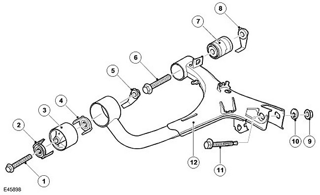
| Item name | Spare part catalog number | Description |
| 1 | - | Bolt |
| 2 | - | Clamp-limiter |
| 3 | - | Front hub |
| 4 | - | Clamp-limiter |
| 5 | - | Castle nut |
| 6 | - | Bolt |
| 7 | - | Rear hub |
| 8 | - | Castle nut |
| 9 | - | Self-locking nut of the upper ball joint of the knuckle |
| 10 | - | Eccentric washer of the upper ball joint of the knuckle |
| 11 | - | Upper ball joint eccentric bolt |
| 12 | - | Upper control arm |
The upper control arm is attached to brackets on the top of the chassis side members. The upper control arm assembly includes a control arm and two bushings. The upper control arm is made of stamped steel. At the outer end of the arm there are two brackets with slotted holes for attaching the upper ball joint of the knuckle. The ball joint is secured to the upper control arm with an eccentric bolt, eccentric washer and self-locking nut. The eccentric bolt and eccentric washer allow you to adjust the camber angle of the wheels.
Two tubular holders are designed to install the front and rear bushings. The bushings, pressed into the holders, are located between the brackets on the chassis side members and are secured with bolts with crown nuts through metal inserts in the center of the bushings.
Comments on this article