Contents: Removal ⇩ Installation ⇩
Removal
1.
CAUTION: Never work on a vehicle supported solely by a jack. Always support the vehicle securely.
Raise and support the vehicle.
2. Remove the wheel and tire assembly.
3.
CAUTION: To avoid contamination of the system, plug all open connections.
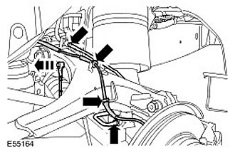
Remove the brake line.
- Disconnect the 2 brake pipe connections.
- Remove the brake hose clamps and release the brake hoses. Release the brake line from the clamp.
4. Disconnect the height sensor connector.
5. Disconnect the wheel speed sensor wire.
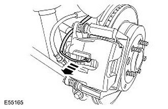
6. Right side only: Release the brake pad wear sensor wire.
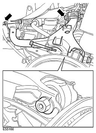
7. Remove the upper control arm.
- Loosen the upper control arm bolts.
- Remember the position of the bolt in relation to the upper arm.
- Remove the nut and bolt, then disconnect the upper control arm from the wheel knuckle.
- Remove the upper control arm bolts.
Installation
1. Install the upper control arm. Insert the bolts, but do not tighten them completely yet.
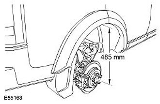
2. Set the distance from the center of the axle shaft to the edge of the wing so that it is 485 mm (19.10 inches). Install a support for the bridge.
3.
CAUTION: Make sure that the ball joint boot is not damaged. Damage to the boot will result in premature failure of the ball joint.
Attach the upper control arm to the wheel knuckle.
- Align the bolt with the marks made earlier.
- Tighten the bolt (tightening torque 133 Nm).
4. Tighten the front upper control arm bolt (tightening torque 175 Nm).
5. Tighten the rear upper control arm bolt (tightening torque 175 Nm).
6. Secure the wheel speed sensor wire.
7. Secure the brake pad wear sensor wire.
8. Attach the height sensor lever.
9. Install the brake pipe. Tighten the brake pipe connections. (tightening torque 175 Nm).
10. Bleed the brake system. For more information, refer to Bleeding the Brake System (70.25.02)
11. Install the wheel and tire assembly. Tighten the wheel nuts. (tightening torque 140 Nm).
12. Adjust the wheel alignment angles.
Comments on this article