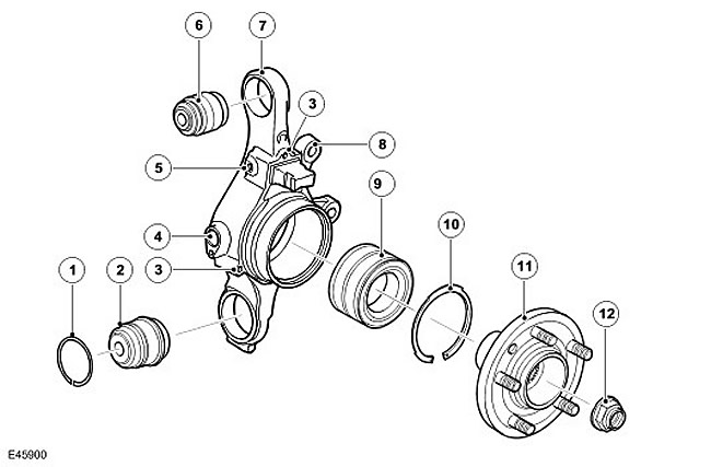
| Item name | Spare part catalog number | Description |
| 1 | - | Lower ball joint retaining ring |
| 2 | - | Lower ball joint |
| 3 | - | Parking brake assembly mounting holes |
| 4 | - | Wheel speed sensor mounting location |
| 5 | - | Wheel Speed Sensor Cable Bracket Mount |
| 6 | - | Upper ball joint |
| 7 | - | Fist |
| 8 | - | Brake caliper mounting holes |
| 9 | - | Wheel bearing |
| 10 | - | Wheel bearing retaining ring |
| 11 | - | Axle nut |
| 12 | - | Wheel hub |
| 13 | - | Wheel studs |
The wheel knuckle is forged and machined and is located between the upper and lower control arms. Two ball joints are pressed into the knuckle. The lower ball joint is secured with a locking ring. The ball joints are located between brackets on the upper and lower control arms and are secured to the arms with bolts and self-locking nuts.
The rear wheel tapered roller bearing is pressed into the hole in the wheel knuckle and secured with a retaining ring. The wheel bearing is a serviceable unit. The knuckle has a hole for installing the wheel speed sensor. Four threaded holes are used to mount the parking brake assembly. The boss on the knuckle is designed to mount the parking brake assembly. Two bosses on the knuckle casting are designed to mount the rear brake caliper.
The wheel hub is cast and machined and pressed into the wheel bearing in the knuckle. The hub has a central hole with splines that match the splines on the axle shaft. Five M14 studs are pressed into the wheel hub to secure the wheel with wheel nuts. The rotation of the axle shaft is transmitted through the splines to the wheel hub, which rotates on a tapered roller bearing.
Comments on this article