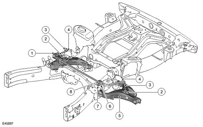
| Item name | Spare part catalog number | Description |
| 1 | - | Right lower control arm |
| 2 | - | Nut for fastening the rack to the lower control arm (2 pcs.) |
| 3 | - | Rack (2 pcs.) |
| 4 | - | Nut for fastening the strut to the stabilizer (2 pcs.) |
| 5 | - | Left lower control arm |
| 6 | - | Bushing (2 pcs.) |
| 7 | - | Bolt (4 pcs.) |
| 8 | - | Bracket (2 pcs.) |
The stabilizer is made from a solid, hardened spring steel rod. The shock absorber is actuated through a pair of struts from their attachment to the lower control arms.
The stabilizer is located on the upper surface of the combined body support and stabilizer brackets welded to each chassis side member. The stabilizer is attached to the brackets by means of two bushings with Teflon inserts. The bushings are equipped with brackets that are pressed into the bushings and attached to the chassis brackets with bolts.
The stabilizer has corrugated "thrust" rings pressed into the inner side of the bushings. The rings prevent lateral movement of the stabilizer.
The ends of the stabilizer are connected to the lower control arms by means of struts. This allows the stabilizer to move together with the wheels, providing maximum efficiency. Each strut has ball joints at both ends. The upper ball joint is connected to the strut at an angle of 90 degrees to its axis. It is installed in a hole in the end of the stabilizer and secured with a self-locking nut. The lower ball joint is connected to the strut at an angle of 90 degrees to its axis. It is installed in a hole in the bracket on the lower control arm and secured with a self-locking nut. The struts are not distinguished by sides and can be installed on either side of the stabilizer.
Comments on this article