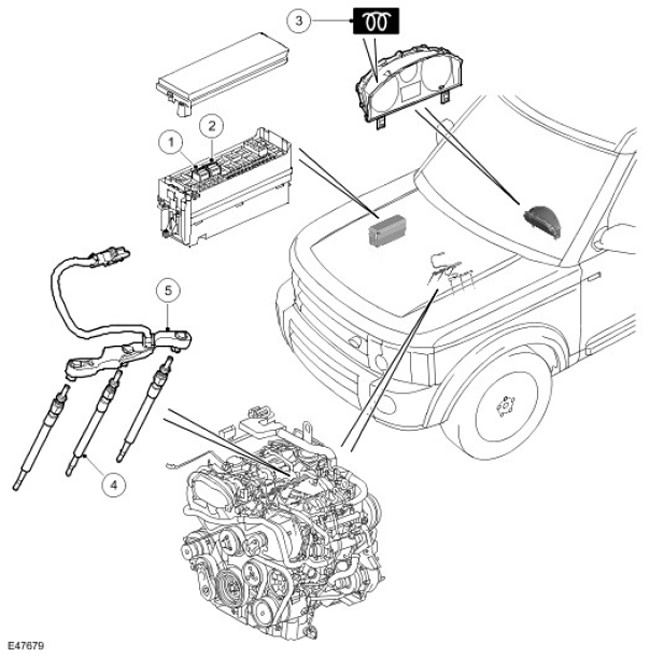
Location of components
| Item name | Spare part number | Description |
| 1 | - | Bank B glow plug relay (left) |
| 2 | - | Bank A glow plug relay (right) |
| 3 | - | Glow plug indicator |
| 4 | - | glow plugs (x 6) |
| 5 | - | Glow plug harness (x 2) |
General provisions
Glow plugs are installed in each cylinder on the intake side. Glow plugs are designed to heat the combustion chambers before and during cranking to facilitate cold engine starting and after engine start to reduce hydrocarbon emissions and cold engine noise at idle.
The glow plug wiring harness for each bank of cylinders is connected to its own relay and its own fuse link in the battery electrical junction box (BJB). Ground connection of each glow plug is provided through its threaded socket in the cylinder head. The glow plug relay is controlled by the ECM, which also controls the glow plug warning light on the instrument panel.
Each glow plug is a tubular heating element with a helical filament that is encased in powdered magnesium oxide. At the tip of the tubular heating element is a heating coil. Behind this spiral, in series with it, a ballast spiral is included. The ballast coil limits the current through the heating coil, preventing it from overheating.
System operation
Glow plug heating is divided into three phases: pre-heating, start-up heating and post-heating. The ECM determines the warm-up duration based on the engine coolant temperature (ECT). The lower the temperature, the longer the heating time.
When the ignition key is turned to position II, the ECM calculates the required warm-up time and, if warm-up is needed, activates the glow plug relay in the BJB. When there is a need for preheating, the ECM sends a request over the high speed CAN bus to turn on the glow plug warning light. The glow plug indicator remains on until the end of the first phase or until the key is turned to start, whichever comes first. If necessary, the ECM leaves the glow plug relay on both when cranking and after starting the engine.
The ECM monitors the power and control circuit of the glow plugs to determine if the power is on, whether it is running continuously, if there is a short or open circuit. When a malfunction is detected, the ECM stores the appropriate DTC and keeps the glow plug warning light on at all times when the ignition key is in position II.
Glow plug control circuit
NOTE: A = Normal Wiring
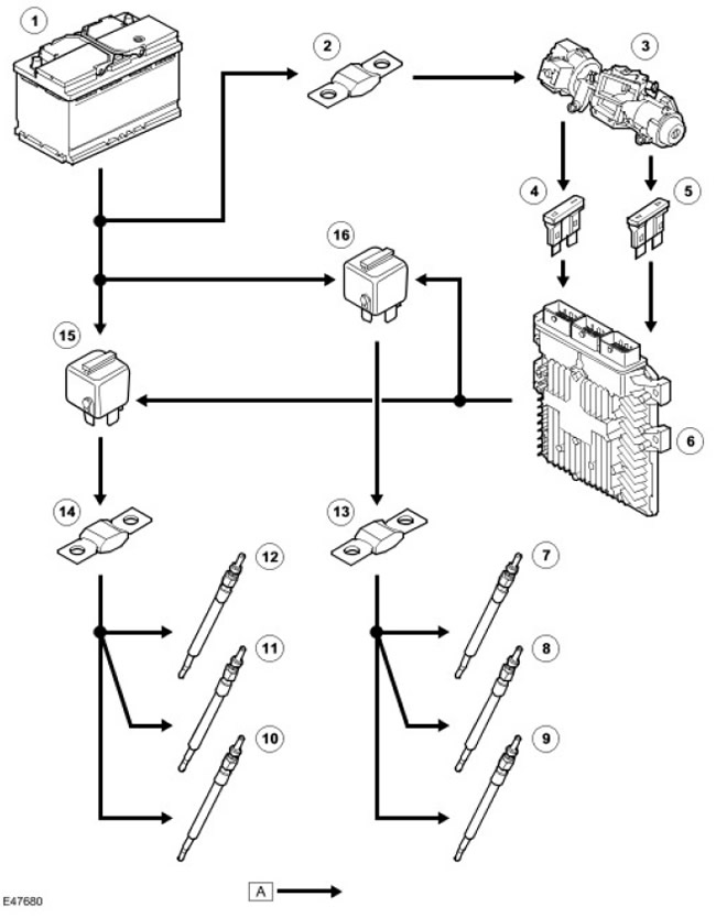
| Item name | Spare part number | Description |
| 1 | - | Accumulator battery |
| 2 | - | Fuse link 11E in BJB block |
| 3 | - | ignition switch |
| 4 | - | 25P fuse in the central electrical box (CJB) (ignition) |
| 5 | - | Fuse 60P in CJB (launch) |
| 6 | - | ECM |
| 7 | - | glow plug 6 |
| 8 | - | glow plug 5 |
| 9 | - | glow plug 4 |
| 10 | - | glow plug 1 |
| 11 | - | glow plug 2 |
| 12 | - | glow plug 3 |
| 13 | - | 4E fuse link in BJB block |
| 14 | - | Fuse link 1E in BJB |
| 15 | - | Bank A glow plug relay (right) |
| 16 | - | Bank B glow plug relay (left) |
Comments on this article