car logo Ford
car logo Volkswagen
car logo BMW
car logo Opel
car logo Audi
car logo Toyota
car logo Peugeot
English Русский
Български
Беларускі
Український
Српски
Hrvatski
Română
Polski
Slovenský
Magyar


Main
Freelander
Discovery
Range Rover
Defender
Contacts
Articles

Lower control arm assembly — removal and installation (Freelander 1)

 
  • Main
  • Freelander
  • Freelander 1
  • Chassis
  • Front suspension
  • Lower control arm assembly — removal and installation
 
        0  
Contents: Dismantling ⇩ Installation ⇩

Dismantling


1. Raise the front of the vehicle.

CAUTION: Do not work under a vehicle supported only by a jack. Always support the vehicle with safety stands.


2. Remove the front wheel.

3. Remove the lower engine protection shield.

EXTERIOR PARTS, REPAIR WORK, Lower engine protection shield.

EXTERIOR PARTS, REPAIR WORK, Lower engine protection shield.


4. Loosen the drive shaft mounting nuts.

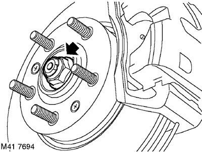
5. With the help of an assistant pressing the brake pedal, unscrew and discard the nut securing the drive shaft to the hub.
5. With the help of an assistant pressing the brake pedal, unscrew and discard the nut securing the…


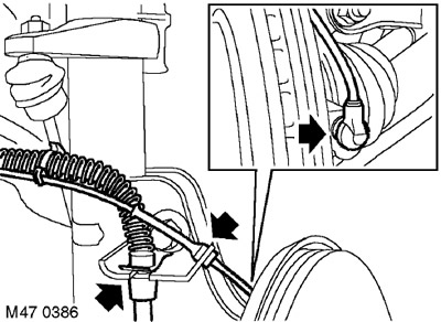
6. Remove the retaining ring securing the brake hose to the shock absorber bracket.

7. Disconnect the wheel speed sensor wiring and the brake hose from the shock absorber.

8. Disconnect the wheel speed sensor wiring from the hub.


8. Disconnect the wheel speed sensor wiring from the hub.


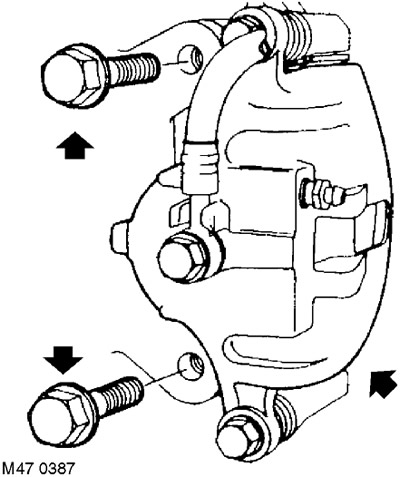
9. Unscrew the two bolts securing the brake caliper to the hub. Remove the caliper from the hub and secure it to the side.

CAUTION: Do not allow the caliper to hang by the brake hose.

CAUTION: Do not allow the caliper to hang by the brake hose.


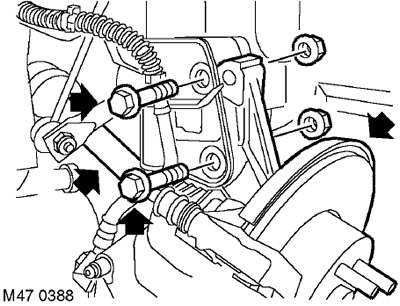
10. Unscrew the two nuts and remove the two bolts securing the hub to the shock absorber strut.

11. Remove the drive shaft from the hub.

12. Secure the drive shaft to the side.
12. Secure the drive shaft to the side.


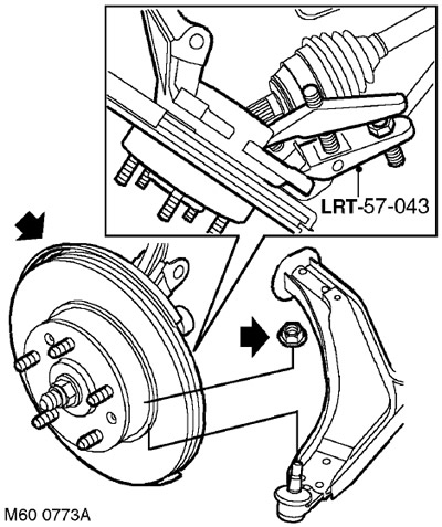
13. Unscrew the lower arm ball joint mounting nut. Discard the nut.


14. Using the LRT-57-043 tool, disconnect the ball joint.

15. Remove the hub assembly.
15. Remove the hub assembly.


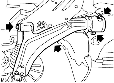
16. Unscrew the 2 bolts securing the rear silent block of the lower arm.

17. Unscrew the bolt securing the front silent block of the lower arm.

18. Remove the lower arm.
18. Remove the lower arm.


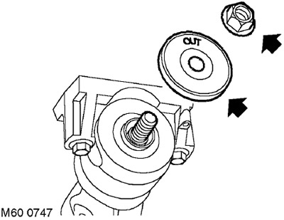
19. Unscrew the rear silent block mounting nut, remove the vibration-protective washer and silent block.

CAUTION: Remember the location of the vibration damper.


Installation


1. Clean the rear silent block mounting surfaces.

2. Install the rear silent block and vibration-proof washer on the lower arm. Screw on the nut, but do not tighten it completely yet.

CAUTION: Make sure the vibration protection washer is positioned correctly. Make sure the "OUT" mark on the washer is visible.


3. Install the lower arm, aligning it with the subframe. Tighten the bolt, but do not tighten it completely yet.

4. Clean the mating surfaces of the lower arm ball joint and hub.

5. Install the hub assembly onto the lower arm. Install a new nut and tighten it to 65 Nm.

6. Clean the drive shaft and hub flange splines from dirt.

7. Insert the drive shaft into the hub.

8. Screw on the new hub nut, but do not tighten it completely yet.

9. Align the hub with the suspension shock absorber strut, install the bolts with nuts and tighten the nuts to a torque of 205 Nm.

10. Position the caliper on the brake disc, install the bolts and tighten them to a torque of 100 Nm.

11. Attach the brake hose to the shock absorber bracket and secure it with a clamp.

12. Clean the surface of the wheel speed sensor, apply anti-seize lubricant to the sensor, and install it on the hub.

CAUTION: Make sure the wheel speed sensor is fully inserted into the hub, i.e. touching the ring gear.


13. Secure the sensor cable to the bracket.

14. Tighten the bolts securing the front silent blocks of the lower arms to a torque of 190 Nm.

CAUTION: When tightening nuts and bolts, the weight of the vehicle must be supported by the suspension.


15. Align the silent blocks, ensuring the correct position of the cylindrical pin. Install the bolts and tighten them to a torque of 105 Nm.

16. Tighten the rear silent block nut to a torque of 140 Nm.

17. Install the new drive shaft mounting nut and tighten it to 400 Nm. Lock the nut onto the end of the drive shaft.


18. Reinstall the lower engine protection shield.

EXTERIOR PARTS, REPAIR WORK, Lower engine protection shield.


19. Reinstall the wheel(s) and tighten the nuts to 115 Nm.

20. Remove the supports and lower the vehicle.


This article is available at russian, bulgarian, belarusian, ukrainian, serbian, croatian, romanian, polish, slovak, hungarian
Article review: Konstantin Nazarov


Previous articles
Anti-roll bar
Anti-roll bars
Rubber pads of the anti-roll bar
Hub bearing — removal and installation
Shock absorber — removal and installation

Current article
Lower control arm assembly — removal and installation

Next articles
Front subframe — removal and installation
Front lower arm silent blocks
Rear lower arm silent blocks


Similar articles from Land Rover repair manuals:
• Lower control arm Discovery 3 (2004-2009)
• Lower control arm ball joints Range Rover 3 (2001-2012)
• Remote control battery Defender 2007+ (2007-2016)

Comments on this article


No comments yet


How much will 47 + 35 =


Freelander 2 
  • General information
  • Using the manual
  • Repair technique
  • Precautionary measures
  • Road test
  • Fault codes
  • Identification codes
  • Jacking and lifting
  • Maintenance - Diesel
  • Maintenance - petrol
  • Chassis
  • Suspension
  • Front suspension
  • Rear suspension
  • Wheels and tires
  • Terrain response
  • Transmission system
  • Cardan shaft
  • Rear drive axle
  • Rear axle shafts
  • Front axle shafts
  • Brake system
  • Parking brake
  • Hydraulic brake
  • Brake booster
  • Anti-lock braking system
  • Exchange rate stability
  • Steering
  • Steering column
  • Power unit
  • Engine device
  • Engine repair
  • Description of the cooling system
  • Cooling system repair
  • Fuel supply
  • Drive units
  • Launch system
  • Ignition system
  • Exhaust toxicity
  • Air filtration
  • Fuel vapor control
  • Electronic control part
  • Automatic gearbox
  • Gearbox cooling
  • Automatic transmission controls
  • Mechanical transmission
  • Transfer case
  • Exhaust system
  • Fuel tank and lines
  • Speed control
  • Electrical equipment
  • Climate control system
  • Climate control
  • Additional climate control
  • Instrument panel
  • Sound signal
  • Information and messages
  • Assistance with parking
  • Battery and alternator
  • Information and entertainment
  • Outdoor Lighting
  • Interior lighting
  • Communication network
  • Wiring harnesses
  • Anti-theft system
  • Multifunctional modules
  • Body and coating
  • Body front panels
  • Lockable body parts
  • Interior trim
  • Rear view mirrors
  • Car seats
  • Glass, frames and mechanisms
  • Instrument panel and console
  • Handles, locks, latches
  • Windshield wipers and washers
  • Sunroof
  • Bumpers
  • Seat belt system
  • Restraint system
  • Body repairs
  • Front end repairs
  • Roof element repairs
  • Side panel repairs
  • Tailgate repairs
  • Subframe and mounts

Freelander 1 
  • General information
  • Using the manual
  • Precautionary measures
  • Technique
  • Specifications
  • Connection tightening torques
  • Maintenance
  • Power unit
  • Diesel engine Td4
  • Petrol engine K1.8
  • Piston group K1.8
  • KV6 petrol engine
  • Piston group KV6
  • Decreased toxicity
  • Motor control EDC
  • Engine management MEMS
  • Motor control Siemens
  • Fuel supply diesel Td4
  • Fuel supply for K1.8 engine
  • Fuel supply of KV6 engine
  • Cooling diesel Td4
  • Engine cooling K1.8
  • Engine cooling KV6
  • Exhaust system Td4
  • Exhaust system K1.8
  • Exhaust system KV6
  • Clutch
  • Mechanical transmission
  • Transfer case
  • Automatic gearbox
  • Chassis
  • Drive shafts
  • Rear axle and final drive
  • Steering
  • Front suspension
  • Rear suspension
  • Brake system
  • Body and coating
  • Passive safety
  • Doors, locks and glass
  • Exterior body parts
  • Interior trim details
  • Seats
  • Roof hatch
  • Roof
  • Body geometry
  • Body parts repair
  • Sealing and corrosion
  • Electrical equipment
  • Heating and ventilation
  • Air conditioning
  • Windshield wipers and washers
  • Starting engine and charging
  • Lighting and headlights
  • Control modules
  • Safety system
  • Window management
  • Entertainment systems
  • Wiring harnesses
  • Governing bodies
  • Devices


LRman.ru © 2013-2026 | Mobile version | Free Lander | Discovery | Range Rover | Defender | Contacts | | Sitemap |
Car repair and service instructions Land Rover: Freelander, Discovery, Range Rover, Defender
We use cookies to make pages load faster and provide a more user-friendly experience 🍪