Contents: Dismantling ⇩ Installation ⇩
Dismantling
1. Raise the front of the vehicle.
CAUTION: Do not work under a vehicle supported only by a jack. Always support the vehicle with safety stands.
2. Remove the front wheel.
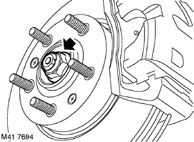
3. Loosen the drive shaft mounting nut.
4. With the help of an assistant pressing the brake pedal, unscrew and discard the nut securing the drive shaft to the hub.
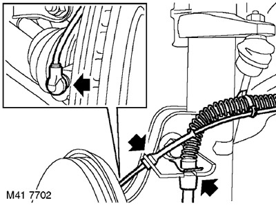
5. Remove the clamp securing the right brake hose to the bracket. Release the hose from the bracket. Release the electrical cable of the wheel speed sensor and brake pad wear sensor from the bracket.
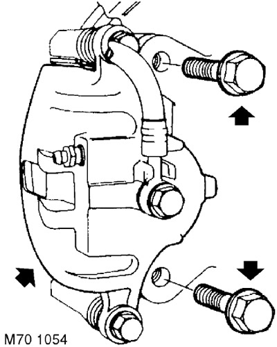
6. Unscrew the two bolts securing the brake caliper to the hub. Remove the caliper from the hub and secure it to the side.
CAUTION: Do not allow the caliper to hang by the brake hose.
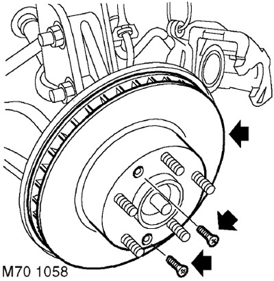
7. Mark the relative positions of the brake disc and hub.
8. Unscrew the 2 brake disc mounting screws and remove the brake disc.
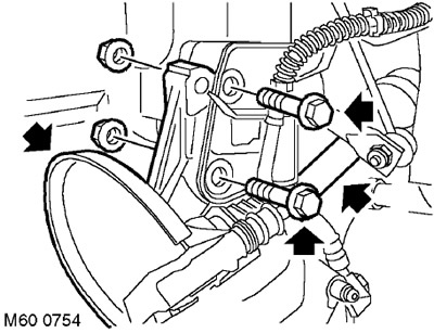
9. Unscrew the two nuts and remove the two bolts securing the hub to the shock absorber strut.
10. Disconnect the hub from the shock absorber strut.
11. Remove the drive shaft from the hub.
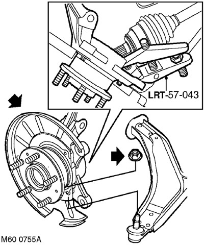
12. While holding the hub from turning, unscrew the nut securing the lower arm ball joint.
13. Using the LRT-57-043 tool, disconnect the ball joint.
14. Remove the hub.
NOTE: If disassembly was performed only to provide access to other system components, no further disassembly operations should be performed.
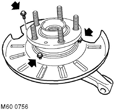
15. Unscrew the 3 bolts securing the brake disc protective cover.
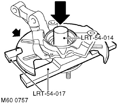
16. Install the hub assembly on the press, placing the LRT-54-017 tool underneath it. Using the LRT-54-014 tool, press out the hub flange.
17. Remove the brake disc protective cover.
NOTE: This will leave the bearing outer race on the hub flange.
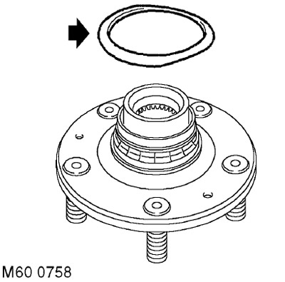
18. Remove the sealing ring from the inner bearing ring.
19. Clamp the hub flange in a vice.
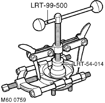
20. Clamp the inner bearing race with both clamps of the appropriate bearing puller so that the inner surfaces of the clamps fit into the groove on the inner race.
For 2002 and later vehicles, there is no groove on the inner race of the bearing. To remove the inner race, grip the bearing puller around the surface of the inner race.
21. Using the LRT-99-500 tool and the LRT-54-014 drift, remove the bearing inner race from the hub flange.
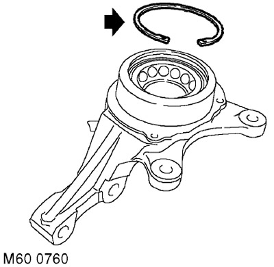
22. Remove the retaining ring from the bearing.
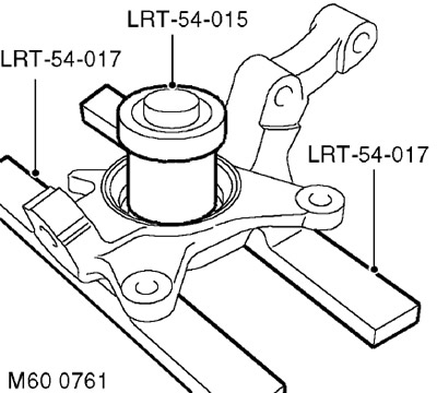
23. Place the hub on a press and using tools LRT-54-015 and LRT-54-017 remove the bearing and discard it.
CAUTION: Never reuse a bearing.
Installation
1. Clean the hub and its flange from dirt.
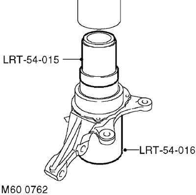
2. Place the LRT-54-016 tool under the hub and press in the new bearing using the LRT-54-015 tool.
CAUTION: One side of the bearing is magnetized. The magnetic side of the bearing can be identified by its matte black surface. The bearing must be installed with the magnetic side facing the inside of the vehicle. Make sure the magnetic side is clean before installing the bearing. Handle the bearing with extreme care.
3. Install the retaining ring onto the hub.
4. Install the brake disc protective cover, install its mounting bolts and tighten them to a torque of 8.5 Nm.
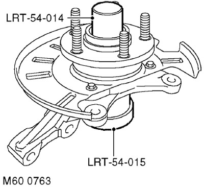
5. Place the LRT-54-015 tool under the bearing and press the hub flange into it using the LRT-54-014 tool.
6. Clean the drive shaft.
7. Install the hub assembly onto the lower arm. Install a new nut and tighten it to 65 Nm.
8. Insert the drive shaft into the hub.
9. Align the hub with the suspension shock absorber strut, install the bolts with nuts and tighten the nuts to a torque of 205 Nm.
10. Clean the mating surfaces of the brake disc and hub flange.
11. After aligning the marks, install the brake disc on the hub flange. Install the screws and tighten them to 5 Nm.
12. Clean the mating surfaces of the brake caliper and hub.
13. Position the caliper on the brake disc, install the bolts and tighten them to a torque of 100 Nm.
14. Secure the brake hose to the bracket and install the clamp.
15. Clean the surface of the wheel speed sensor, apply lubricant to prevent the sensor from seizing, and install it on the hub.
CAUTION: Make sure the wheel speed sensor is fully inserted into the hub, i.e. touching the ring gear.
16. Secure the sensor cable to the bracket.
17. Install the new drive shaft mounting nut and tighten it to 400 Nm. Lock the nut onto the end of the drive shaft.
18. Lock the nut.
19. Reinstall the wheel(s) and tighten the nuts to 115 Nm.
20. Remove the supports and lower the vehicle.
Comments on this article