Contents: Dismantling ⇩ Installation ⇩
Dismantling
1. Disconnect the negative battery terminal.
2. Raise the front of the vehicle.
CAUTION: Do not work under a vehicle supported only by a jack. Always support the vehicle with safety stands.
3. Remove the front wheel.
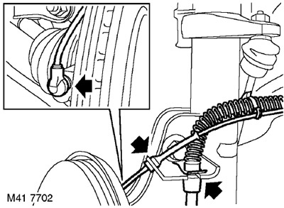
4. Remove the retaining ring securing the brake hose to the shock absorber bracket.
5. Disconnect the wheel speed sensor wiring and the brake hose from the shock absorber.
6. Release the wheel speed sensor from the hub mounting.
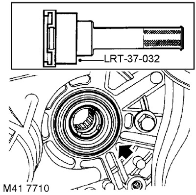
7. Unscrew the two bolts securing the brake caliper to the hub. Remove the caliper from the hub and secure it to the side.
CAUTION: Do not allow the caliper to hang by the brake hose.
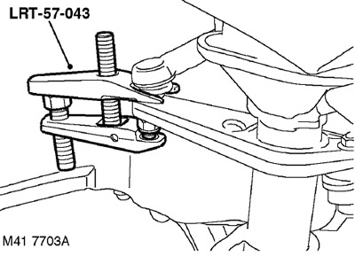
8. Loosen the nut securing the steering rod to the steering arm and use the LRT-57-043 tool to disconnect the ball joint.
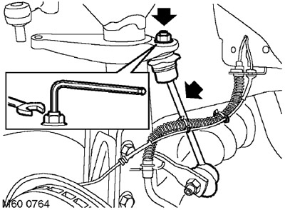
9. Loosen the upper nut securing the anti-roll bar, disconnect the anti-roll bar and move it to the side.
CAUTION: Use a wrench and Allen key to prevent the ball joint from rotating when removing the stabilizer link.
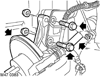
10. Unscrew the two nuts and remove the two bolts securing the hub to the shock absorber strut.
11. Disconnect the shock absorber strut from the hub.
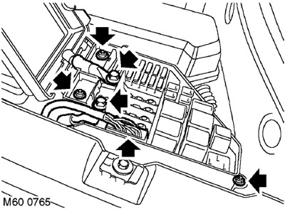
12. Left side: Remove the 2 bolts securing the negative and positive electrical wires to the fuse box.
13. Left side: Disconnect the multi-pin connector from the fuse box located in the engine compartment.
14. Left side: Disconnect the electrical wires and move them to the side.
15. Left side: Unscrew the 3 nuts securing the fuse box and move the box to the side.
16. Right side: Loosen the engine cooling system expansion tank mounting bolt and move the tank to the side.
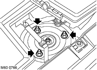
17. Mark the location of the upper shock absorber strut support relative to the body.
18. Unscrew the 3 nuts securing the upper shock absorber support and remove the spring and shock absorber assembly.
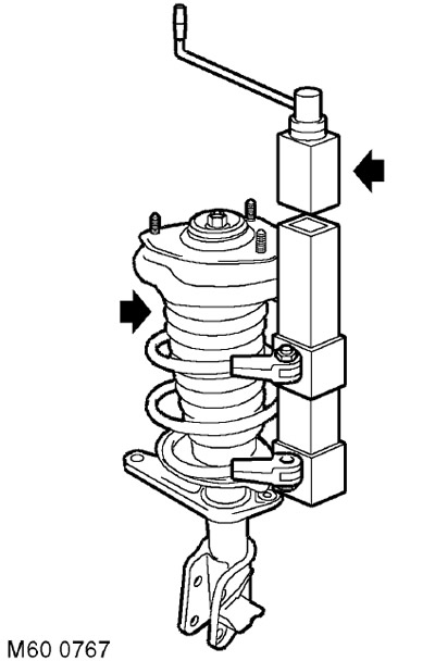
19. Clamp a suitable spring compressor in a vice.
20. Install the spring and shock absorber assembly into the fixture. Compress the spring.
CAUTION: Pay attention to the relative position of the upper support, spring and protective cover of the shock absorber.
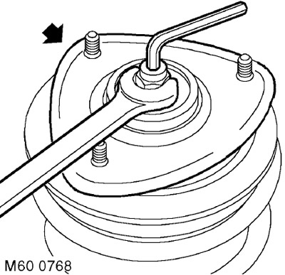
21. Compress the spring by 2-3 cm to release the upper support. Holding the shock absorber rod with an Allen key, unscrew and discard the upper support mounting nut.

22. Remove the washer and upper support.
23. Remove the support plate and compression stroke limiter.
24. Remove the upper spring support cup, protective boot and compression stroke limiter support.
25. Remove the shock absorber from the spring.
26. Release the spring and remove it from the device.
Installation
1. Inspect the shock absorber, spring cup rubber pads and upper support bearing for wear and damage.
2. Clean the mating surfaces of the spring and its support cups.
3. Clean the shock absorber rod and the compression stop support.
4. Install the spring and shock absorber assembly into the fixture. Compress the spring.
5. Assemble the shock absorber and spring. Make sure the spring is located in the recess of the lower spring support cup.
6. Install the compression stop support and the shock absorber protective cover onto the shock absorber.
7. Install the compression stroke limiter and support plate.
8. Install the upper spring support cup and washer.
9. While holding the shock absorber piston rod with an Allen key, install the new nut and tighten it to 57 Nm.
CAUTION: Pay attention to the relative position of the upper support, spring and protective cover of the shock absorber.
10. Release the spring and remove it from the device.
11. Clean the seating surface of the upper support.
12. Install the shock absorber strut and align the upper support with the body. Install the nuts and tighten them to a torque of 45 Nm.
13. Left side: Install the fuse box. Screw on the nuts and tighten them to 8 Nm.
14. Left side: Connect the positive and negative electrical cables, install the bolts and tighten them to 8 Nm.
15. Left side: Connect the multi-pin connector to the fuse box.
16. Right side: Install the engine cooling system expansion tank and secure it with the bolt.
17. Align the hub with the shock absorber strut, install the bolts with nuts and tighten the nuts to a torque of 205 Nm.
18. Clean the anti-roll bar ball joint and its mounting surface.
19. Connect the anti-roll bar, screw on a new nut and tighten it to a torque of 55 Nm.
CAUTION: Use a wrench and Allen key to prevent the ball joint from rotating when installing the stabilizer link.
20. Clean the steering rod ball joint and its mounting surface.
21. Connect the ball joint to the steering arm, install a new nut and tighten it to 55 Nm.
22. Clean the surface of the wheel speed sensor, apply anti-seize lubricant, and install it on the hub. CAUTION: Make sure that the wheel speed sensor is fully inserted into the hub, i.e. touches the ring gear.
23. Secure the wheel speed sensor wiring and brake hose to the bracket and secure them with a clamp.
24. Reinstall the wheel(s) and tighten the nuts to 115 Nm.
25. Remove the supports and lower the vehicle.
26. Connect the negative battery terminal.
Comments on this article