car logo Ford
car logo Volkswagen
car logo BMW
car logo Opel
car logo Audi
car logo Toyota
car logo Peugeot
English Русский
Български
Беларускі
Український
Српски
Hrvatski
Română
Polski
Slovenský
Magyar


Main
Freelander
Discovery
Range Rover
Defender
Contacts
Articles

Flexible pipes and hoses (Freelander 1)

 
  • Main
  • Freelander
  • Freelander 1
  • General information
  • Technique
  • Flexible pipes and hoses
 
        0  
Contents: General information ⇩ Engine fuel system hoses ⇩ Engine cooling system hoses ⇩ Relative position of the hose and…⇩ Clamps ⇩ Protection against overheating of…⇩

General information


When removing and installing flexible pipes and hoses, follow the instructions listed below. This is a guarantee of reliable and long-lasting operation.
  • Before removing brake or power steering hoses, thoroughly clean the hose connections and surrounding area.
  • Before disconnecting the hoses, obtain suitable plugs or caps. After disconnecting the hose, immediately plug the openings in the housing or fitting to prevent dirt from entering the system.
  • Clean the removed hoses from the outside and blow them out with compressed air from the inside. Carefully inspect the removed hose. Pay attention to the presence of cracks, cord delamination, and the reliability of the sealing of the tips. All hoses that are damaged cannot be reinstalled.
  • When installing the hose, avoid sharp bends. After tightening the fastening nuts, the hose should not be twisted.
  • After removing the hose, seal the connecting nipple with a cap; and close the hydraulic unit itself.
  • When working with hydraulic system components, absolute cleanliness must be maintained at all times.
  • After any work on hydraulic systems, check for leaks. To do this, one person should be under the car and carefully inspect the connection points, and the other, while driving the car, should press the brake pedal as hard as possible or turn the steering wheel with the engine running.

Do not disconnect any air conditioner lines unless you are qualified and trained to do so. The refrigerant used in the air conditioner can cause blindness if it comes into contact with your eyes.


Engine fuel system hoses
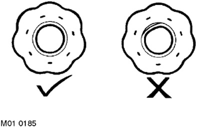

Engine fuel system hoses


All fuel hoses are designed with two layers: an outer layer of reinforced rubber and an inner layer of special rubber. When removing any fuel hose, carefully inspect its inner layer. The inner layer should not have any delaminations from the outer casing made of cord rubber. If delamination is detected, the hose should be replaced with a new one.

Engine cooling system hoses


It is ESSENTIAL to follow the instructions below to avoid damage to the cooling system hoses and the fittings connected to them.

Relative position of the hose and the branch pipe
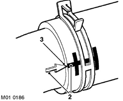

Relative position of the hose and the branch pipe


To avoid damage or fatigue failure of the hose, the hose must be connected to the connecting pipe correctly.

The source of the article is located on the website www.LRman.ru


If the hose and branch pipe have pairing marks (2), they should only be connected in this position.

During installation, the hose should be completely placed on the connecting pipe. Usually, there is a special shaped boss (3) on the pipe, allowing the connection to be assembled correctly.

Clamps
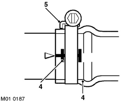

Clamps


Usually the hose has marks (4) on it that indicate the correct position of the clamp. If there are no marks, the clamp should be positioned directly behind the flange at the end of the connecting pipe, as shown in the figure.

The flange of the clamp (5) with the worm must be directed towards the near end of the hose.

Otherwise, the hose may become pinched between the clamp and the flange of the branch pipe.

Worm drive clamps should be tightened to 3 Nm unless otherwise specified.

After tightening the clamp, make sure that the clamp does not touch adjacent parts.
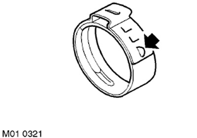
After tightening the clamp, make sure that the clamp does not touch adjacent parts.


The "Oetiker" type clamps are disassembled after unbending the tongue (shown by the arrow in the figure) and releasing the outer branch of the clamp. Clamps of this type are not subject to further use. When installing a new clamp, ensure the correct position of the clamp on the hose, when tightening the clamp, align the tongue with the longitudinal slot on the outer branch of the clamp (shown by the arrow in the figure).


Protection against overheating of parts


All required heat and protective screens must be installed and in good condition. If damage to these elements is visible, they must be replaced.

Pay attention to the installation of hoses adjacent to very hot engine parts, such as the exhaust manifold and exhaust gas recirculation (EGR) lines.

When heated, the hoses will deform. This must be taken into account when laying and securing the hoses.


This article is available at russian, bulgarian, belarusian, ukrainian, serbian, croatian, romanian, polish, slovak, hungarian
Article review: Konstantin Nazarov


Previous articles
General recommendations when performing plumbing work
Ball and roller bearings
Oil seals
Joints and butt surfaces
Locking parts of connections
Parts with cylindrical threads
Bolt Designations
Designation of nuts

Current article
Flexible pipes and hoses

Next article
Using roller stands for road testing


Similar articles from Land Rover repair manuals:
• Flexible pipelines And hoses Discovery 3 (2004-2009)
• Windshield washer hoses Discovery 1 (1989-1998)
• Flexible pipes and hoses Range Rover 3 (2001-2012)

Comments on this article


No comments yet


How much will 21 + 23 =


Freelander 2 
  • General information
  • Using the manual
  • Repair technique
  • Precautionary measures
  • Road test
  • Fault codes
  • Identification codes
  • Jacking and lifting
  • Maintenance - Diesel
  • Maintenance - petrol
  • Chassis
  • Suspension
  • Front suspension
  • Rear suspension
  • Wheels and tires
  • Terrain response
  • Transmission system
  • Cardan shaft
  • Rear drive axle
  • Rear axle shafts
  • Front axle shafts
  • Brake system
  • Parking brake
  • Hydraulic brake
  • Brake booster
  • Anti-lock braking system
  • Exchange rate stability
  • Steering
  • Steering column
  • Power unit
  • Engine device
  • Engine repair
  • Description of the cooling system
  • Cooling system repair
  • Fuel supply
  • Drive units
  • Launch system
  • Ignition system
  • Exhaust toxicity
  • Air filtration
  • Fuel vapor control
  • Electronic control part
  • Automatic gearbox
  • Gearbox cooling
  • Automatic transmission controls
  • Mechanical transmission
  • Transfer case
  • Exhaust system
  • Fuel tank and lines
  • Speed control
  • Electrical equipment
  • Climate control system
  • Climate control
  • Additional climate control
  • Instrument panel
  • Sound signal
  • Information and messages
  • Assistance with parking
  • Battery and alternator
  • Information and entertainment
  • Outdoor Lighting
  • Interior lighting
  • Communication network
  • Wiring harnesses
  • Anti-theft system
  • Multifunctional modules
  • Body and coating
  • Body front panels
  • Lockable body parts
  • Interior trim
  • Rear view mirrors
  • Car seats
  • Glass, frames and mechanisms
  • Instrument panel and console
  • Handles, locks, latches
  • Windshield wipers and washers
  • Sunroof
  • Bumpers
  • Seat belt system
  • Restraint system
  • Body repairs
  • Front end repairs
  • Roof element repairs
  • Side panel repairs
  • Tailgate repairs
  • Subframe and mounts

Freelander 1 
  • General information
  • Using the manual
  • Precautionary measures
  • Technique
  • Specifications
  • Connection tightening torques
  • Maintenance
  • Power unit
  • Diesel engine Td4
  • Petrol engine K1.8
  • Piston group K1.8
  • KV6 petrol engine
  • Piston group KV6
  • Decreased toxicity
  • Motor control EDC
  • Engine management MEMS
  • Motor control Siemens
  • Fuel supply diesel Td4
  • Fuel supply for K1.8 engine
  • Fuel supply of KV6 engine
  • Cooling diesel Td4
  • Engine cooling K1.8
  • Engine cooling KV6
  • Exhaust system Td4
  • Exhaust system K1.8
  • Exhaust system KV6
  • Clutch
  • Mechanical transmission
  • Transfer case
  • Automatic gearbox
  • Chassis
  • Drive shafts
  • Rear axle and final drive
  • Steering
  • Front suspension
  • Rear suspension
  • Brake system
  • Body and coating
  • Passive safety
  • Doors, locks and glass
  • Exterior body parts
  • Interior trim details
  • Seats
  • Roof hatch
  • Roof
  • Body geometry
  • Body parts repair
  • Sealing and corrosion
  • Electrical equipment
  • Heating and ventilation
  • Air conditioning
  • Windshield wipers and washers
  • Starting engine and charging
  • Lighting and headlights
  • Control modules
  • Safety system
  • Window management
  • Entertainment systems
  • Wiring harnesses
  • Governing bodies
  • Devices


LRman.ru © 2013-2026 | Mobile version | Free Lander | Discovery | Range Rover | Defender | Contacts | | Sitemap |
Car repair and service instructions Land Rover: Freelander, Discovery, Range Rover, Defender
We use cookies to make pages load faster and provide a more user-friendly experience 🍪