Contents: Removal ⇩ Installation ⇩
Note: On later models, the lock-up solenoid is not serviceable separately from the selector lever.
Removal
1. Disconnect the battery.
2. Remove the selector handle and the illumination panel.
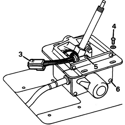
3. Disconnect the wiring connector.
4. Loosen the selector mechanism mounting bolts and remove it from the housing.
5. Loosen the screws securing the microswitch bracket.
6. Loosen the screws securing the side panel of the selector housing and remove the panel.
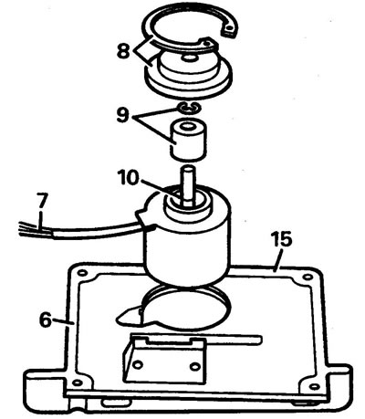
7. Disconnect the locking solenoid connector.
8. Remove the retaining ring and support cover.
(Data taken from the website lrman.ru)
9. Remove the retaining ring and center sleeve.
10. Remove the solenoid.
Installation
11. Install the solenoid into the side cover of the selector mechanism housing.
12. Install the bushing and new retaining ring.
13. Install the support cover and retaining ring.
14. Connect the wiring connector.
15. Apply Silcoset 152 or equivalent sealant to the side cover flange.
16. Lubricate all moving parts of the selector mechanism with Rocol E1A grease or its equivalent.
17. Reinstall the removed parts.
Selector lock microswitch (in the selector mechanism housing)
1. Disconnect the battery.
2. Remove the selector handle and the illumination panel.
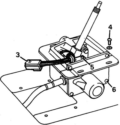
3. Disconnect the wiring connector.
4. Loosen the selector mechanism mounting bolts and remove it from the housing.
5. Loosen the screws securing the microswitch bracket.
6. Loosen the screws securing the side panel of the selector housing and remove the panel.
7. Disconnect the connector.
8. Remove the three retaining rings, see figure.
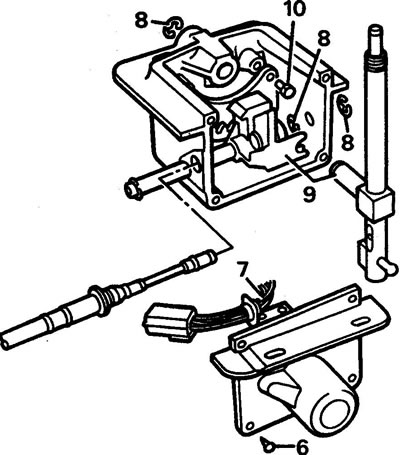
9. Move the selector lever shaft forward and remove the lever.
10. Loosen the bolt securing the selector position control board.
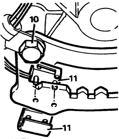
11. Remove the microswitch mounting clip and the microswitch.
12. Installation is carried out in reverse order.
Selector lock microswitch (on the side cover)
1. Disconnect the battery.
2. Remove the selector handle and the illumination panel.
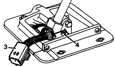
3. Disconnect the wiring connector.
4. Loosen the screws securing the microswitch bracket.
5. Disconnect the microswitch connector.
6. Installation is carried out in reverse order.
Comments on this article