Note: After checking the electronic control unit, the fault codes must be cleared. Refer to the "Self-Diagnostics" section.
Note: Due to the small size of the electronic unit terminals, we recommend using an adapter connector to connect measuring instruments.
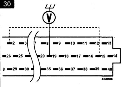
Checking the supply voltage - Figure 30
Technical conditions
| Contacts | State | Voltage |
| 15 and mass | Ignition OFF | battery |
| 2 and mass | Ignition ON | battery |
| 19 and mass | Ignition ON | battery |
Make sure the ignition is off.
Disconnect the electrical connector from the electronic control unit.
Measure the voltage between the wiring connector terminal and ground.
Turn on the ignition.
Measure the voltage between the terminals of the wiring harness connector and ground.
If the voltage is not within specifications, check the wiring and relay.
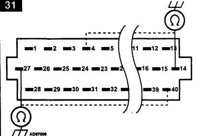
Checking the Ground Circuit - Figure 31
Technical conditions
| Contacts | Resistance |
| 4 and mass | zero |
| 14 and mass | zero |
| 27 and mass | zero |
| 40 and weight | zero |
Make sure the ignition is off.
Disconnect the electrical connector from the electronic control unit.
Measure the resistance between the wiring connector contacts and ground.
If the resistance differs from the specified value, check the wiring.
Comments on this article