Contents: Checking the supply voltage - Figure…⇩ Checking the ground circuit - Figure…⇩ Functionality check - Figure 19 ⇩
Note: The ignition system amplifier is located on the high voltage distributor.
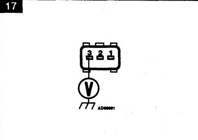
Checking the supply voltage - Figure 17
Technical conditions
| Contacts | Position | Voltage |
| 3 and mass | Ignition ON | battery |
Make sure the ignition is off.
Disconnect the ignition amplifier electrical connector.
Turn on the ignition.
Measure the voltage between the wiring connector terminal and ground.
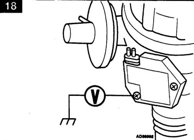
Checking the ground circuit - Figure 18
Technical conditions
| Contacts | Position | Voltage |
| Screw and mass | Ignition ON | Maximum 0.1 V |
Turn on the ignition.
Measure the voltage between the ignition amplifier mounting screw and ground.
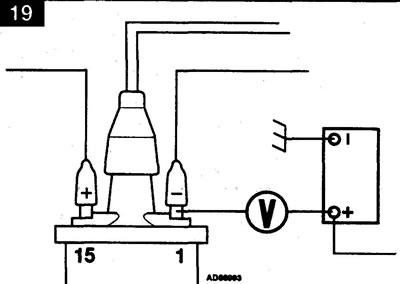
Functionality check - Figure 19
Technical conditions
| Contacts | Operation | Voltage |
| 1 and (+) of the battery | Ignition OFF | Zero |
| 1 and (+) of the battery | Ignition ON | Zero |
| 1 and (+) battery | Starter cranking | Increase in voltage |
Note: To prevent the engine from starting when cranking the engine, disconnect the injector connectors.
Make sure the ignition coil and ignition amplifier connectors are connected.
Strip the contacts of the low voltage terminals of the ignition coil.
Measure the voltage between coil 1 terminal and the "+" terminal of the battery.
Turn on the ignition.
Measure the voltage between coil 1 terminal and the "+" terminal of the battery.
(The original text can be found at: LRman.ru)
Turn the engine over with the starter.
Measure the voltage between coil 1 terminal and the "+" terminal of the battery.
Comments on this article