Contents: Dismantling ⇩ Installation ⇩
Dismantling
1. Remove the timing cover gasket.
ENGINE - Td4, Inlet and outlet camshafts, Timing gear cover gasket.
2. Remove the rear crankshaft oil seal.
ENGINE - Td4, Inlet and outlet camshafts, Replacement of rear crankshaft oil seal.
3. Remove the connecting rod bearings.
ENGINE - Td4, Piston group, Replacement of connecting rod bearings.
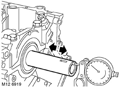
4. To measure the crankshaft end play, set the dial indicator as shown in the figure, move the crankshaft back and set the indicator to "zero". Move the crankshaft in the opposite direction and read the indicator reading.
TECHNICAL SPECIFICATIONS, Engine - Diesel Td4.
5. Remove the 10 bolts securing the main caps to the cylinder block and save them for future use.
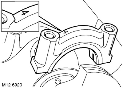
6. Carefully remove the main caps, remembering that cap No.4 has a bearing with a thrust flange. Lay out the main caps in the order in which they were installed on the engine.
7. Remove the crankshaft from the cylinder block.
8. Remove the liners from the cylinder block and main caps and dispose of them.
9. Wipe the crankshaft, thoroughly blow out all oil channels.
10. Wipe the main caps and bearing beds in the cylinder block, blow dry the main bolt seats.
11. Wipe the old main bolts and lightly lubricate their threaded portion with oil.
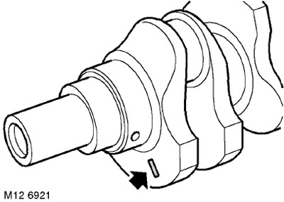
12. The main journal size group can be identified by the color mark on the front counterweight, if this mark is visible. If the mark cannot be found, then measure the diameter of the main journals.
13. Measure the diameter of each main journal in four directions at an angle of 90, record the measurement results, determine the ovality of the journals. Compare the measurement results with the technical specifications.
TECHNICAL SPECIFICATIONS, Engine - Diesel Td4.
14. If the ovality of the journals of the nominal or 1st repair size is higher than the permissible value, they can be ground to the next repair size.
15. If the ovality of the journals is within acceptable limits, but the diameter, due to natural wear, is less than that indicated by the color code, then when measuring the gap using a deformable gauge, it is necessary to install liners of increased thickness (within one repair size) in the block and in the covers.
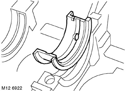
16. Install the inserts of the selected thickness into the block and into the covers, remembering that cover No.4 must contain an insert with a thrust flange.
NOTE: Only those bearings marked with a yellow mark should be installed in the cylinder block. The oil clearance is adjusted by replacing the bearings in the main caps. Ignore the colored marks on the cylinder block walls.
17. Place the crankshaft into the cylinder block.
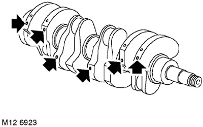
18. Check the color marks on the crankshaft counterweights as shown in the figure.
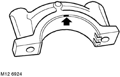
19. Insert the liners with marks of the same color (the marks are located on the edge of the liners) into the main caps, remembering that the liners with a thrust flange are installed in cap No.4.
20. Place a strip of deformable gauge (Plastigage) on the main journal.
21. Install the main caps and old main bolts. Tighten the main bolts in a diagonal pattern to
20 Nm, then turn them by 70°. Check the crankshaft axial play again.
CAUTION: When measuring the clearance with a deformable gauge, do not turn the crankshaft.
22. Sequentially loosen and remove the main bolts, remove the main caps and liners.
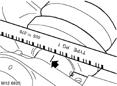
23. Using a special ruler, measure the width of the calibration strip and, based on this value, determine the gap size on each main journal.
TECHNICAL SPECIFICATIONS, Engine - Diesel Td4.
24. If the values do not correspond to the technical conditions, then you need to select another insert(s) from the size group and repeat the gap measurement.
25. Remove the crankshaft and remove all traces of calibration strips from the main journals using clean engine oil and a cloth.
26. Install the bearing shells that have been found to be good into the main caps.
27. Lubricate the main journals and main bearings that have been found to be in good condition with clean engine oil.
28. Install the main caps and old main bolts.
29. Tighten the bolts to 20 Nm and then turn them an additional 70°.
30. Install a dial indicator on the end of the crankshaft nose, move the crankshaft back and set the indicator to zero.
31. Move the crankshaft forward and read the indicator reading.
TECHNICAL SPECIFICATIONS, Engine - Diesel Td4.
32. If the axial clearance value does not correspond to the technical specifications, then select a thrust insert with a different flange thickness, but with the same color code. Inserts with three flange thickness values are produced.
33. Install the selected liners into both the block and the main cover.
34. Install the main caps and old main bolts. Tighten the main bolts in a diagonal pattern to
20 Nm, then turn them by 70°. Check the crankshaft axial play again.
TECHNICAL SPECIFICATIONS, Engine - Diesel Td4.
35. If the axial clearance is within the permissible limits, then: Loosen and remove the main bolts in sequence. Discard the bolts.
Installation
1. Lightly coat the threaded portion of the new main bolts with engine oil and screw them into the cylinder block.
2. Tighten the main bolts diagonally to 20 Nm, then turn them an additional 70°.
3. Install the connecting rod bearings.
ENGINE - Td4, Piston group, Replacement of connecting rod bearings.
4. Install the timing cover gasket.
ENGINE - Td4, Inlet and outlet camshafts, Timing gear cover gasket.
5. Install the rear crankshaft oil seal.
ENGINE - Td4, Inlet and outlet camshafts, Replacement of rear crankshaft oil seal.
Comments on this article