Location of elements
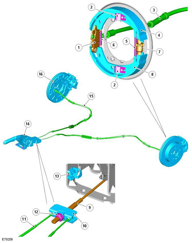
| Pos. | spare part no | Name |
| 1 | - | parking brake extension |
| 2 | - | Brake Shoe Clip (2 pcs.) |
| 3 | - | Parking brake cable sheath bushing |
| 4 | - | Upper (secondary) brake shoe |
| 5 | - | Brake Shoe Mounting Spring |
| 6 | - | Brake Shoe Return Spring |
| 7 | - | Mechanical brake pad adjuster |
| 8 | - | Lower (primary) brake shoe |
| 9 | - | Parking brake lever cable |
| 10 | - | Parking brake cable equalizer |
| 11 | - | Parking brake cable |
| 12 | - | Equalizer fastening element |
| 13 | - | Parking brake microswitch |
| 14 | - | Parking brake lever assembly |
| 15 | - | Parking brake cable sheath |
| 16 | - | Dust guard brake |
The parking brake is a manually operated drum brake system built into the rear brake discs. The inner center portion of the rear brake disc is shaped to form a brake drum.
Brake pads assy
The brake pads are mounted horizontally on the integrated brake dust shield and brake shield, forming a system with upper secondary and lower primary brake pads. The locking pins pass through the holes in the dust shield and the corresponding holes in the brackets of each brake shoe. Each pin is attached to the brake shoe with a spring clip. The pins allow the brake shoe to move towards the drum surface during parking brake operation, but prevent the brake shoe from moving sideways away from the dust shield.
The expander and the mechanical regulator are located along the horizontal axis of the dust shield. The expander is located at the front of the dust shield and houses the primary and secondary ends of the brake shoe brackets. The mechanical adjuster is mounted at the rear of the dust shield and houses the anchor point for the opposite ends of the brake shoe brackets.
The mechanical regulator is used to adjust the gap between the friction lining of the shoe and the drum during maintenance. The handwheel of the mechanical knurled adjuster is accessed through a hole in the front of the brake disc. Adjustment is necessary when replacing brake pads or discs. A burn-in procedure is also required to ensure that drum brakes perform satisfactorily. For more information, see the chapter: Breaking in the parking brake pads (206-05 Parking Brake and Parking Brake Actuator, General Procedures).
The contact of the corresponding ends of the brackets of the upper and lower brake shoes with the expander and the mechanical regulator is supported by two return springs. Return springs are located between the ends of each upper and lower brake shoe and are fixed in holes on the brake shoe brackets. When the parking brake is released, the return springs pull the brake shoes away from the drum.
Parking brake lever
The parking brake lever is located on the floor console, between the driver and passenger seats, it has a toothed sector and a push button-operated locking mechanism. One cable with a threaded stud connects the sector to the leveling block and is fastened with a lock nut or a nut with a washer.
The threaded stud allows the parking brake cable tension and parking brake lever travel to be adjusted during service. For more information, see chapter: Parking brake cable adjustment (206-05 Parking Brake and Parking Brake Actuator, General Procedures).
The parking brake cable exits from the parking brake lever equalizer and runs along the chassis to the rear parking brake extension. The parking brake cable protrudes from the front of the dust shield and has a ferrule that connects to the extension. The opposite ends of each left and right parking brake cables are equipped with a ferrule that connects to an equalizing block. The equalizer serves to ensure that the left and right parking brake mechanisms work simultaneously when the parking brake is activated.
A microswitch is located on the base of the parking brake lever. When the parking brake is activated, the microswitch turns on the parking brake indicator lamp located in the instrument panel. For more information, see chapter: Instrument panel (413-01 Instrument panel, Description and function).
Comments on this article