Contents: Removal ⇩ Installation ⇩
Special tool
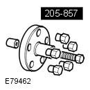 205-857 Remover, Halfshaft 205-857 Remover, Halfshaft | 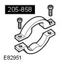 205-858 Remover, Halfshaft Inboard Joint 205-858 Remover, Halfshaft Inboard Joint | 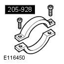 205-928 Remover, Half Shaft Inboard Joint 205-928 Remover, Half Shaft Inboard Joint |
To avoid damaging the ball joint, do not allow the axle shaft to hang loose on one side.
To avoid damage to the ball joint, do not store or install axle shafts in the fully folded position.
AAR type roller joints (Angularly Adjusted Roller), mounted on the inside of some axle shafts, do not have an internal retaining mechanism and can therefore become separated.
Removal
1. Raise and support the vehicle.
WARNING: Ensure that the vehicle is supported securely.
2. Drain the oil from the differential.
3. Remove the wheel and tire assembly. Refer to the procedure: Wheel and Tire (204-04 Wheels and Tires, Removal and Installation).
4, Loosen the rear axle shaft nut.
NOTE: Left side shown, same for right side.
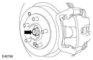
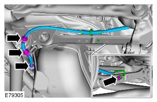
5. Remove the stabilizer link. Refer to the procedure: Rear Stabilizer Link (204-02 Rear Suspension, Removal and Installation).
6.
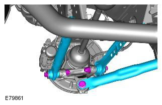
7.
NOTE: Left side shown, same for right side.
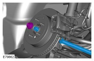
8. Loosen and discard the rear axle nut.
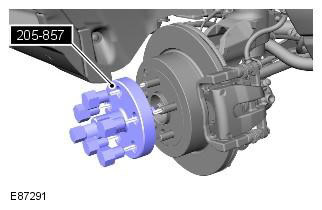
9. Disconnect the rear axle shaft. Special tool: 205-857
NOTE: Left side shown, same for right side.
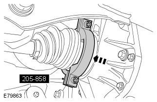
10. Install the special tool on the rear axle inner joint housing. Special tool: 205-858
NOTE: Cars manufactured before MY 2010.
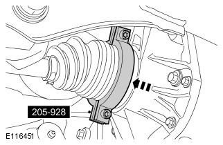
11. Install the special tool on the rear axle inner joint housing. Special tool: 205-928
NOTE: Vehicles produced since MY 2010.
12. Place a container to catch any spilled oil.
13. With the help of an assistant, remove the rear axle shaft.
Installation
1. Clean the parts.
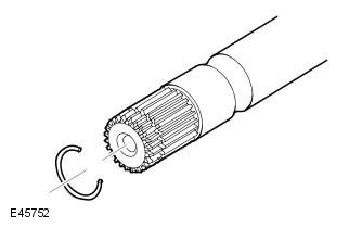
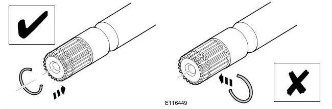
2. Install a new snap ring onto the rear axle shaft and, with the help of a partner, attach the inner CV joint to the differential.
Be very careful not to damage the seal.
Make sure the snap ring is installed on the end side of the axle shaft. Failure to do so may result in damage to the vehicle.
3. Remove and discard the rear axle shaft seal guard.
NOTE: The axle shaft seal guard should separate into two pieces.
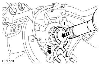
4. With the help of an assistant, install the rear axle shaft into the hub.
5. Install the new rear axle nut. Do not tighten it fully at this stage.
CAUTION: At this stage, tighten the nuts only by hand.
6. Attach both lower control arms to the hub assembly. Do not fully tighten at this stage.
CAUTION: At this stage, tighten the nuts and bolts only finger tight.
7. Attach the trailing arm to the hub assembly. Do not tighten fully at this stage.
CAUTION: At this stage, tighten the nut and bolt only finger tight.
8. Connect the parking brake cable.
9. Place the jack under the rear hub of the vehicle.
10.
- Tighten the nuts and bolts of both lower arms. Tightening torque: 175 Nm
- Tighten the trailing arm nut and bolt. Tightening torque: 270 Nm
- Tighten the rear axle nut. Tightening torque: Step 1: 330 Nm. Step 2: 30°
- Secure the hub nut with a caulking pin.
Nuts and bolts must be tightened when the vehicle is supported by the suspension.
Do not use an air tool to install the nut. Failure to do so may result in damage to this component.
11. Install the stabilizer link. Refer to the procedure: Rear Stabilizer Link (204-02 Rear Suspension, Removal and Installation).
12. Install the wheel. Refer to the procedure: Wheel and Tire (204-04 Wheels and Tires, Removal and Installation).
13. Fill the differential with the required amount of oil.
CAUTION: Do not fill the differential up to the filler plug hole. The filler plug hole is used only to fill the differential with oil and is not intended to be used as a level indicator.
Comments on this article